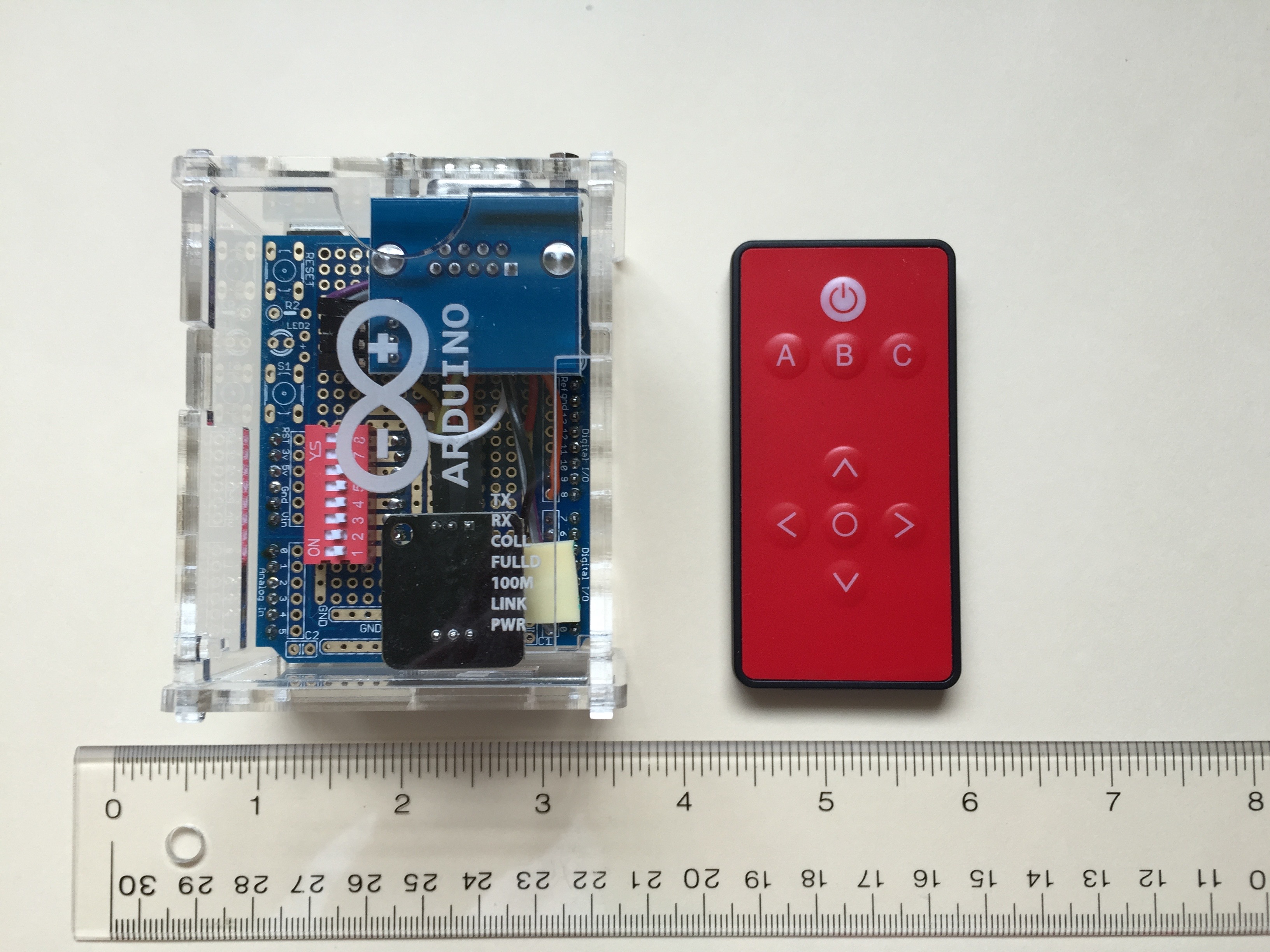
The Controller 2020 is a small infrared system for controlling Lionel TMCC CAB-1 and Legacy
Engines, Switches, and Accessories. The infrared range exceeds my ability to test.
It performs flawlessly at distances greater than forty (40) feet.
Figure 1. The Controller 2020 Module And Remote
To use the Controller 2020 you need a working
Lionel 6-14295 #990 Legacy Command Set
and a
Lionel 6-81326 LCS Serial Converter 2
You also need additional cables as described in the Lionel documentation. See for example, the
Lionel SER2 User's Guide.
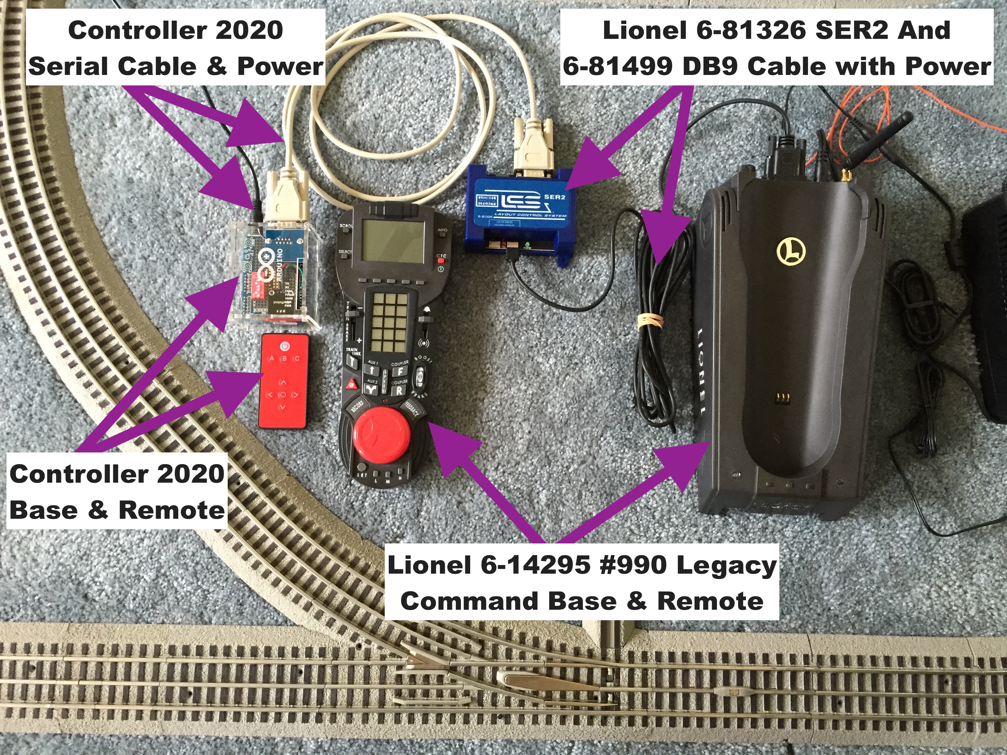
Once you have properly connected the Lionel SER2 to your working Legacy setup, simply
connect the Controller 2020 to the Lionel SER2 with a 9 pin serial cable. A somewhat busy Figure 2 below shows
the entire system.
The cable connecting the Controller 2020 to the SER2 is a RS-232 DB9 Serial Cable like would be
used for connecting a PC serial port to an external device. The device, in this case the Lionel
SER2, is expected to have a 9 pin female connector and the Controller 2020, which pretends to be
a PC, has a 9 pin male connector. The cable is a "straight-through" serial cable with a female
connector on one end and a male connector on the other. It is NOT a "null-modem" cable.
You probably have a suitable cable in an old junk bin - although you may have to modify it some
to fit on the Controller 2020's thick acrylic case. Modification details can be found
here.
Figure 2. The Controller 2020 Connected To Lionel A Legacy System
Notes:
Controller 2020 is trademarked and the content of this site is copyrighted.
The Controller 2020 is not "ruggedized". Dropping it may crack or shatter the acrylic
case and/or damage the circuit board or loosen connections. It's not delicate
but you should treat it well - like you would one of your trains.
This device is not FCC certified. Go here for more information.
The thick acrylic enclosure of the Controller 2020 may prevent RS232 cables found in your
junk box from fitting well. Go here for more information.
Some pictures on these pages show the circuit board on shipping foam. These pictures
show red foam but that will vary. Your Controller 2020 may be delivered with red,
blue, black, white, or any color foam.
The color of wires and ribbon cable used in the Controller 2020 may vary.
The circuit board(s) may vary depending on suppliers, shipping times, and cost.
Specifically, any given Controller 2020 may use an Arduino Uno or some type of Uno clone.
All are tested and verified to work.
Lionel Legacy Control (sometimes called TMCC2) is a newer and enhanced version of the
CAB-1 (sometimes called TMCC1) command set. However, some newly introduced Lionel products
such as the Command Control Tie-Jectors (Lionel 6-81444 through 6-81448) and the TMCC
Speeders (Lionel 6-37063 through 6-37068) operate exclusively on TMCC1 commands. All TMCC2
products are backward compatible with TMCC1 so the Controller 2020 design decision was to
use the more universal TMCC1 commands wherever possible. Specifically, all devices, all
Accessories, Switches, Engines, Tie-Jectors, and Speeders are controlled exclusively using
TMCC1 commands. Most Engine FEATURES are also controlled with TMCC1 commands.
TMCC1 Control Details
Speed for Engines, Tie-Jectors, and Speeders
Direction for Engines, Tie-Jectors, and Speeders
Front and Rear Couplers for Engines, Tie-Jectors, and Speeders
Blowing the Horn
Ringing the Bell
Ejecting Tie-Jector Ties
Turning Speeder Headlights and Strobe on and off
The only operations controlled by TMCC2 commands are
Once you have connected your Controller 2020 as pictured in Figure 2 the magic can begin - and
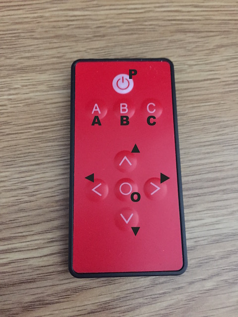
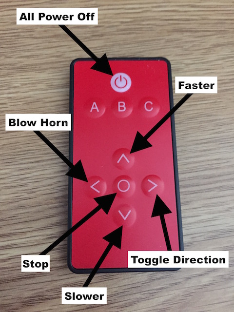
your magic wand is the little infrared remote control. Figure 3 shows the remote with a legend
of characters superimposed on the image. These superimposed characters will be used in the
following discussion to describe operation of The Controller 2020.
Figure 3. The Controller 2020 Remote's Character Legend
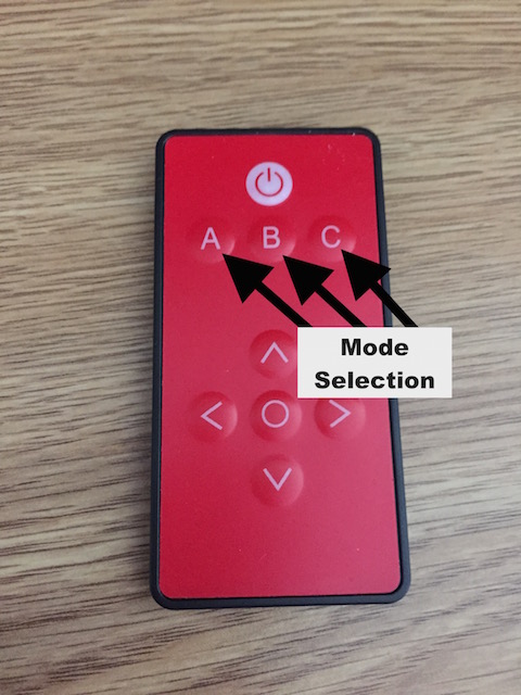
Perhaps the most important thing to understand about the Controller 2020 is that it has
three modes of operation: Mode A, Mode B, and Mode C. Selection of the mode is pretty
obvious. As you might guess, pressing A enters Mode A and so on. Figure 4 summarizes
mode selection.
Figure 4. Mode Selection With The Controller 2020 Remote
The active mode tells the module how to interpret an infrared command. For example, if
Mode A is active the module interprets an infrared command as defined by pins 1 & 2 of
the configuration dipswitch. Mode B processes the command as defined by pins 3 & 4 and
Mode C as defined by pins 4 & 5. So, if Mode B is active and pins 3 & 4 are both
OFF (equal zero) the remote will control Lionel Legacy Engine number one.
Only one mode can be active at a time and that mode is determined by pressing A, B, or C
on the remote. In the factory configuration the user would touch B to select Engine 1 and
press ▲ a couple of times to get the engine going. Later she would press A to control a
Switch and press ▶ to tell Switch 1 to turn.
Using the configuration dipswitch the user can set Mode A to control Engine 1, Mode B to
control Engine 2, and Mode C to control Engine 2 Features like opening the couplers and
enabling smoke. Other configurations can be set with the dipswitch as described below.
Soft Configuration
must be used to access Lionel Legacy Command Control Accessories, Engines, and Switches with
Lionel LCS IDs higher than 2.
The following picture summarizes operation of the remote when it is in a Mode that controls an Engine.
Note the difference between pressing O and pressing P. O stops the engine you are controlling.
P is emergency power off. It stops everything.
Figure 5. The Controller 2020 Remote: Engine Control
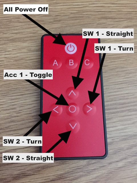
The next picture summarizes operation of the remote when it is in a Mode that controls a Switch.
Again P is emergency power off. However, when the remote is controlling Switches it can also
toggle the behavior of an Accessory with LCS ID 1. That is, in this Mode the remote controls two Switches
but also commands one Accessory by sending the two command sequence: "Aux1 Option 1" + "Numeric 1".
This is the same sent by ▲ in Accessory Mode and will cause a momentary closure of output 1 on the
ASC2 in both 1 TMCC ID and 8 TMCC ID configurations. It can also toggle the latched output of
Electric RailRoad Company modules.
Figure 6. The Controller 2020 Remote: Switch Control
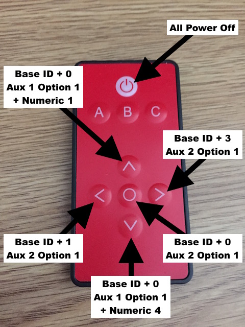
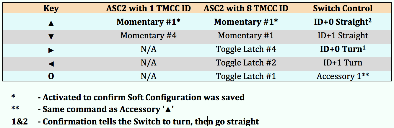
This next picture summarizes operation of the remote when it is controlling an Accessory.
Accessory control is a little more complicated than, say, making an Engine go faster. Specifically,
Lionel documents 18 distinct Accessory action commands and the Lionel 6-81639 ASC2, often a target of
these commands, can be operated in three different ways:
Momentary closure with 8 sequential LCS IDs assigned to the ASC2. Momentary closure of a
single output occurs when an Aux1 key is sent from the 990 handset to the associated ID.
Latching closure with 8 sequential LCS IDs assigned to the ASC2. A single output toggles
between latched closed and latched open when an Aux2 key is sent from the 990 handset to the
ID associated with the desired output.
Momentary contact closure with a single LCS ID assigned to the ASC2. This setup is most
often used when the ASC2 is used to control uncoupler tracks. The 990 handset fires the
specific uncoupler when you press the Aux1 key immediately followed by a digit between 1 and 8.
The simple explanation is the Controller 2020 sends combinations of Accessory commands as shown in
Figure 7 - to provide the control summarized in Figure 11. For those of you wanting a more complete
explanation, we have a Technical Deep Dive.
Technical Deep Dive
You don't need to know the details of the LCS Command Specification to use the 990 handset but it's
a different story if you want to build your own controller. Following are the commands that cause
specific ASC2 operation.
8 TMCC ID momentary closure:
Aux1 Option1 sent to the ID of the output you want to momentarily close.
8 TMCC ID latching closure:
Aux2 Option1 sent to the ID of the output whose latch state you want to toggle.
1 TMCC ID requires a two command sequence (the outputs are always momentary closure):
Aux1 Option1 sent to the base ID of the ASC2.
Numeric Command sent to the base ID of the ASC2 where the 'numeric' is that of the output you want to momentarily close.
As shown in Figure 7 following, the Controller 2020 actually sends two commands when some of the
IR remote keys are pressed. I found that the second command is ignored by the ASC2 when it is in
8 TMCC ID mode, but is used by the ASC2 when it is in 1 TMCC ID mode. Sending two commands this
way allows me to "piggy-back" operation between the two ASC2 configurations using the same IR remote key.
Note that the Electric RailRoad Company's Mini Commander (and other products) can be configured to
latch an output instead of momentarily closing the output when it receives the Aux1 Accessory command.
I've done this in my Searchlight project and toggle the light on and off with the Aux1 key instead of
the Aux2. This allows me to operate it with the O key when the remote is in Switch control mode.
Figure 7. The Controller 2020 Remote: Accessory Control
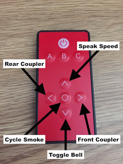
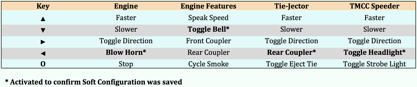
Finally, the following picture summarizes operation of the remote when it is controlling
Engine Features.
Figure 8. The Controller 2020 Remote: Engine Feature Control
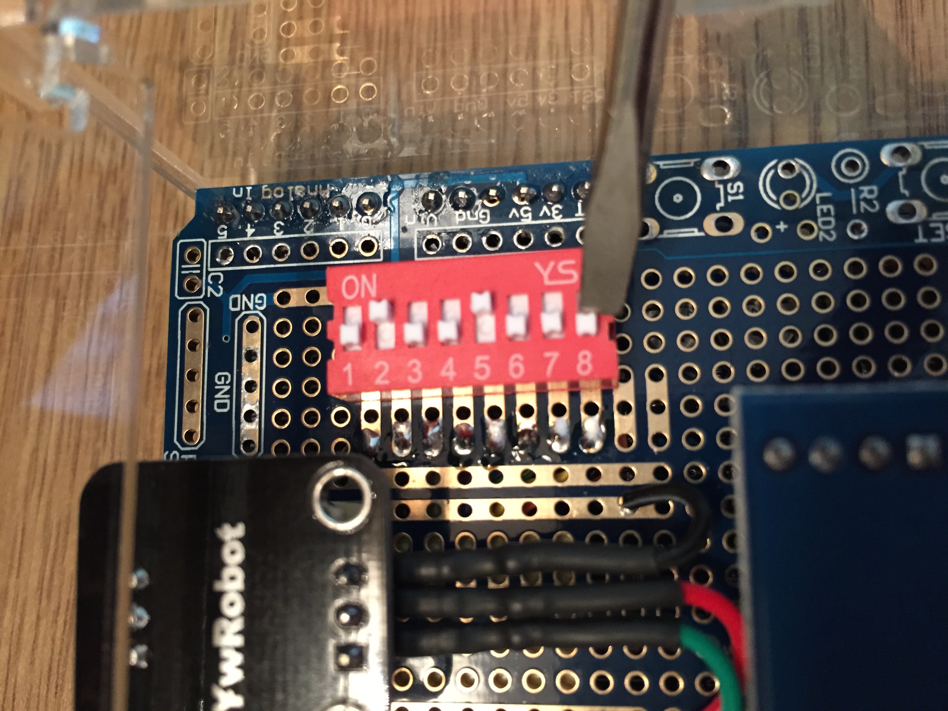
Configuration Switch Settings
An important advantage of The Controller 2020 is the ability to customize it for your personal
use. This can be done in several ways, the easiest of which is to change the settings of the
dipswitch on top of the circuit board. The switch has eight pins - their meaning is explained
following Figure 9. To change the configuration remove power, flip open the enclosure lid, and
set the pins as desired. This is most easily done using the blade of a small screwdriver.
Figure 9 shows the tip of a screwdriver blade on pin eight.
The pins are numbered from left to right and this may be a little confusing at first since
this is the reverse of normal numbers that have the smaller digit to the right. The picture
shows the factory configuration - the way The Controller 2020 is shipped. Pins 1 & 2 set the
behavior of Mode A as described below. Notice that pin 2 is 1 (ON) and pin 1 is 0 (OFF).
Look at the description for "pin1 & pin2" below and make sure you
understand the numbering. Again, pin 1 is on the left, pin 2 is on the right.
Note: The dipswitch settings are only read at power up. To change these settings disconnect
the power, change the switch settings as desired, then re-apply power. Don't be touchin' The
Controller 2020 board with power connected!
Figure 9. The Controller 2020 Configuration Dipswitch
pin1 & pin2: Determine command processing for Mode A (factory default setting is bold)
00 - Control Accessory 1
10 - Control Engine 1 (Speed, Direction, Horn)
01 - Control Switches 1 & 2, Toggle Accessory 1
11 - Control Engine 1 Features (Bell, Couplers, Smoke, Dialog)
pin3 & pin4: Determine command processing for Mode B (factory default setting is bold)
00 - Control Engine 1 (Speed, Direction, Horn)
10 - Control Engine 2 (Speed, Direction, Horn)
01 - Control Engine 1 Features (Bell, Couplers, Smoke, Dialog)
11 - Control Switches 1 & 2, Toggle Accessory 1
pin5 & pin6: Determine command processing for Mode C (factory default setting is bold)
00 - Control Engine 1 (Speed, Direction, Horn)
10 - Control Engine 2 (Speed, Direction, Horn)
01 - Control Engine 1 Features (Bell, Couplers, Smoke, Dialog)
11 - Control Engine 2 Features (Bell, Couplers, Smoke, Dialog)
pin7: Controls Grandkids Operation (factory default setting is bold)
0 - Grandkids Operation OFF
1 - Grandkids Operation ON. Grandkids operation limits the top speed of Engines to about
60% of maximum to help prevent your little darlings from destroying your expensive train.
pin8: Enables/Disables an alternative interpretation of the pins (factory default setting is bold)
0 - Standard meaning
1 - Alternative interpretation. This "alternative interpretation" of the pins is described following.
Alternative Switch Interpretation
Setting pin 8 of the dipswitch to ON specifies an alternative operational/debuging/testing interpretation of pins 1-6.
The meaning of pin 7 (Grandkids Operation) stays the same.
pin1 & pin2: Alternative Interpretation - Log Control
00 - No operation defined (NOOP). Recommended setting when using an operation
specified by other pins (such as defining a new Soft Configuration).
10 - Ten seconds after powering up the Controller 2020 will print the internal log to the
serial port as ASCII text. The serial cable must be disconnected from the Lionel SER2
and connected to the serial port of a PC or Mac running
a terminal emulator program. Set the terminal emulator to 9600 BAUD, no parity.
The log will be displayed on the terminal emulator. The 10 second delay is arbitrary -
It just seemed like a good thing to do.
01 - Ten seconds after powering up the Controller 2020 will clear its internal log.
I didn't want to do this immediately upon power up so I arbitrarily chose a 10 second delay.
11 - Reserved
pin3 & pin4: Alternative Interpretation - Configuration Control
00 - No operation defined (NOOP). Recommended setting when using a previously defined
Soft Configuration.
10 - Ten seconds after powering up the Controller 2020 will print the current configuration
to the serial port as ASCII text. The serial cable must be disconnected from the Lionel
SER2 and connected to the serial port of a PC or Mac
running a terminal emulator program. Set the terminal emulator to 9600 BAUD, no parity.
01 - Ten seconds after powering up the Controller 2020 will delete any Soft Configurations
and restore the factory default configuration.
11 - Define Soft Configurations
pin5: (No Alternative Interpretation)
0 - No operation defined (NOOP). The recommended setting when using an operation
specified by other pins.
1 - Reserved
pin6: Alternative Interpretation - Debugging
0 - Normal Operation. Debugging OFF.
1 - Turn debugging ON. Do NOT do this when the Controller 2020 is connected to a SER2.
pin7: Stays The Same
0 - Grandkids Operation OFF
1 - Grandkids Operation ON. This of course has no meaning when defining a new Soft Configuration or
displaying the log or current configuration - so leave this pin OFF when in those circumstances.
pin8: Alternative Interpretation
0 - N/A (Alternative Interpretation not enabled)
1 - Use the Alternative Interpretation
Soft Configuration
Recall that the A, B, and C buttons on the IR remote represent three independent Modes - each of which
is always configured to control some Lionel LCS device. When first power up the Controller 2020 activates
mode B (it had to start in one of the three...) but a simple press of an A, B, or C IR remote key instantly
changes the active Mode.
Some target device is always commanded in each Mode and when the Controller 2020 is powered up with pin8 OFF
the "standard interpretation" of the dipswitch pins configures a predefined assignment of a device to each
of the three Modes. This "standard interpretation" allows you to quickly and easily choose the targets you
want to command from a small number of well defined options. By using Soft Configurations, however, you can
truly customize your Controller 2020 in an almost unlimited number of ways. You can, for example, assign
Mode A to Engine ID 33, Mode B to Switches 59 and 60, Mode C to the Features of Engine ID 7.
To define a Soft Configuration, set pins 3, 4, and pin 8 of the dipswitch to ON (1), all the other
pins OFF (0), then power up the Controller 2020 and begin entering a Soft Configuration command.
When pins 3, 4, and 8 are ON and the other pins are OFF the definition of a new Soft Configuration
is enabled. The Controller 2020 is waiting for you to press P on the remote. Soft Configuration
commands are of variable length but all begin by pressing the Power key on the remote. That is, set a
new Soft Configuration by pressing P followed by the parameters
x, y, z, z, z... where:
The first parameter entered, x, must be A, B, or C.
As previously mentioned, there are three modes: Mode A, Mode B, and Mode C.
Pressing PA begins the process of setting the configuration of Mode A, pressing
PB begins setting Mode B, and PC setting Mode C. Additional infrared button
presses are expected to immediately follow. These will complete the new definition of the
specified Mode.
Example:
PA: Says we are starting to define Mode A operation. More IR key presses are expected.
The next infrared remote key, y in the above sequence, continues the configuration of the
Mode previously specified by the x key. This additional key selects the
device to be controlled. Device choices are:
A: Says we want to configure an Accessory. Accessories initially have an ID of '1'.
B: Says we want to configure an Engine. Engines initially have an ID of '1'.
C: Says we want to configure a Switch. Soft Configuring a Switch starts with
a base ID of '1' just like an Engine. However, when a Mode that controls a Switch is
active the remote actually controls two Switches with sequential IDs plus one Accessory
with an ID of '1'. More infrared keys are expected to complete this Soft Configuration
but the Accessory controlled by the O key on the remote cannot be changed. The
remote O key can only ever control the Accessory with ID '1'. The intention is
to activate an uncoupler track connected to a Lionel ASC2 (6-81639).
O: Says we want to configure Engine Features. This also has an initial ID of '1'.
▲: Says to configure a Tie-Jector. Again, the initial ID is '1'.
▼: Says to configure a TMCC Speeder. Like you would expect, the initial ID is '1'.
Examples:
PAA: Says we want to define Mode A to control an Accessory.
More infrared keys are expected.
PAB: Says we want to define Mode A to control an Engine. More infrared
keys are expected.
PBC: Says we want to define Mode B to control a Switch (and also toggle
Accessory 1 as shown in Figure 6). More infrared keys are expected.
The next infrared remote key, z in the above sequence, may be repeated and
continues the configuration progress by setting the ID of the chosen device. This
is done by entering combinations of one or more of the following four keys:
▲: Says to increment the device ID by one (1). IDs greater than 99 are not allowed.
▼: Says to decrement the device ID by one (1). IDs less than 1 are not allowed.
▶: Says to increment the device ID by five (5). IDs greater than 99 are not allowed.
◀: Says to decrement the device ID by five (5). IDs less than 1 are not allowed.
O: Says to increment the device ID by twenty (20). IDs greater than 99 are not allowed.
Examples:
PAB▲: Says we are configuring Mode A to control an Engine and to then increment the
Engine LCS ID by 1. As noted previously, Engine's configured in this fashion
start with an ID of 1. Hence this command has configured an Engine ID of 2.
Since there is not yet a final P, more infrared keys are expected.
PAB▲▲▲: Says we are configuring Mode A to control an Engine and to then increment the
Engine LCS ID by 3 to an ID of 4. Again, since there is not yet a final P, more infrared
keys are expected.
PAB▶: Says we are configuring Mode A to control an Engine and to then increment the
Engine LCS ID by 5 to 6. More infrared keys are expected.
PAC▶▲: Says we are configuring Mode A to control a Switch and to then increment the
Switch LCS ID by 5+1 to 7. More infrared keys are expected.
PAC▲▶: Says we are configuring Mode A to control a Switch and to then increment the
Switch LCS ID by 1+5 to 7 (note the reversed order). More infrared keys are expected.
PAAP: This command is complete and sets Mode A to control the Accessory with LCS ID 1
PAB▲▲▲P: This command is complete and sets Mode A to control the Engine with LCS ID 4
PCO▲▲▲P: This command is complete and sets Mode C to control the Features of the Engine with LCS ID 4
The following are wrong. They are examples of poorly formed Soft Configuration commands:
PBBB: This is wrong. The first three keys (PBB) are OK. Remember, the sequence
of keys is Pxyz where z may be repeated. Here an x key of
B says were are defining Mode B and the y key of B says we want an Engine but the z
key must be some combination of ▲, ▼, ▶, ◀, or O.
POA: This is wrong because O is not a legal second, or x, key.
The 'x' key, the second key, must be one of A, B, C.
A final 'P' says we are done - save the configuration.
Special Note: Soft Configuration commands are limited to 16 IR remote key presses.
This means the following command, intended to set Mode A to an Engine with ID 16, is
illegally long and will have unpredictable results.
PAB▲▲▲▲▲▲▲▲▲▲▲▲▲▲▲P
To set Mode A to an Engine with ID 16 use instead one of the following commands.
PAB▶▶▶P
PAB◀OP
PABO◀P
PAB▶▶▲▲▲▲▲P
Soft Configuration Final Notes
Once you have entered the ending P you have completed the definition of a Soft
Configuration. You may define another by pressing P and again entering
the x, y, z, z, z...,P sequence.
You may exit Soft Configuration definition by unplugging the Controller 2020 and setting "pin3 & pin4" to OFF.
To be taught a Soft Configuration the Controller 2020 must of course be powered on. However, it is not
absolutely necessary that the track or Soft Configuration target be powered. That is only
necessary to allow the Controller 2020 to issue the confirmation.
Once you have defined a Soft Configuration it is permanently stored in memory. It is saved
until you define a new Soft Configuration or restore the factory default configuration.
The three Soft Configurations are initially defined as the Mode A, B, and C jumper settings marked
as DEFAULT. To revert the Soft Configurations to these initial settings:
Disconnect the Controller 2020 from power.
Set the dipswitches as described under "pin3 & pin4" of the above
Alternative Interpretation discussion.
Connect the Controller 2020 to power. After ten seconds the original configuration will be restored.
Wait 20 seconds to be sure then disconnect the power.
Set the dipswitches for some other operation.
To use your personalized Soft Configurations remove power, flip open the enclosure lid, and
set pin 8 ON with all other dipswitch pins OFF. Reapply power and you are ready to control
your customized devices.
Soft Configuration Confirmation
After you hit the Soft Configuration ending P the target device is briefly activated to
confirm the entered Soft Configuration command was well formed and was accepted and saved. Specific
device confirmation depends on the type of target (remember the target must be powered to be activated):
Accessory: Momentary closure of ASC2 output 1 (listen closely for the click)
Engine: Blows the horn
Engine Feature: Rings the bell
Switch: Tells the Switch with the base ID to Turn Out, pauses, then sets it to Pass Through
Command Control Tie-Jector: Activates the Rear Coupler (listen closely for the buzz)
TMCC Speeder: Flashes the headlights (watch carefully)
Soft Configuration Device Control Summary
Soft Configuration allows control of numerous Lionel Legacy or TMCC enabled products
as summarized in the following figures.
Figure 10. IR Remote Engine Control Summary
Figure 11. IR Remote Accessory And Switch Control Summary
Debugging
CAB-1 and Lionel Legacy Commands (TMCC1 & TMCC2) are documented
here.
They are binary commands that the 990 Legacy Command Base modulates onto the outer rails of your
track layout. The Controller 2020 normally uses a Lionel SER2 to inject these binary commands
into your layout. Turning on debugging, however, tells the Controller 2020 to instead convert the binary
commands into human readable hexadecimal ASCII text. In addition, internal Arduino program
information is displayed such as state transitions and each IR remote key as it is pressed.
This is just a little bit of geek paradise. You're welcome!
To Enable Debugging:
Remove power from The Controller 2020
Disconnect the Controller 2020's serial cable from the SER2
Set dipswitch pins 6 and 8 ON. Other pins may also be ON depending on what you are doing.
Connect the Controller 2020's serial cable to a PC/Mac running a terminal emulator program
as shown in Figure-12 below.
Apply power to the Controller 2020. Debugging information will immediately be displayed at
9600 BAUD, no parity, 1 stop bit.
WARNING: Never enable debugging OR print logs OR print configurations when the
Controller 2020 is connected to your Lionel system.
TMCC1 and TMCC2 enabled devices (Engines, Switches, etc.) listen for the TMCC binary
commands and could be very confused or perhaps even damaged by ASCII text.
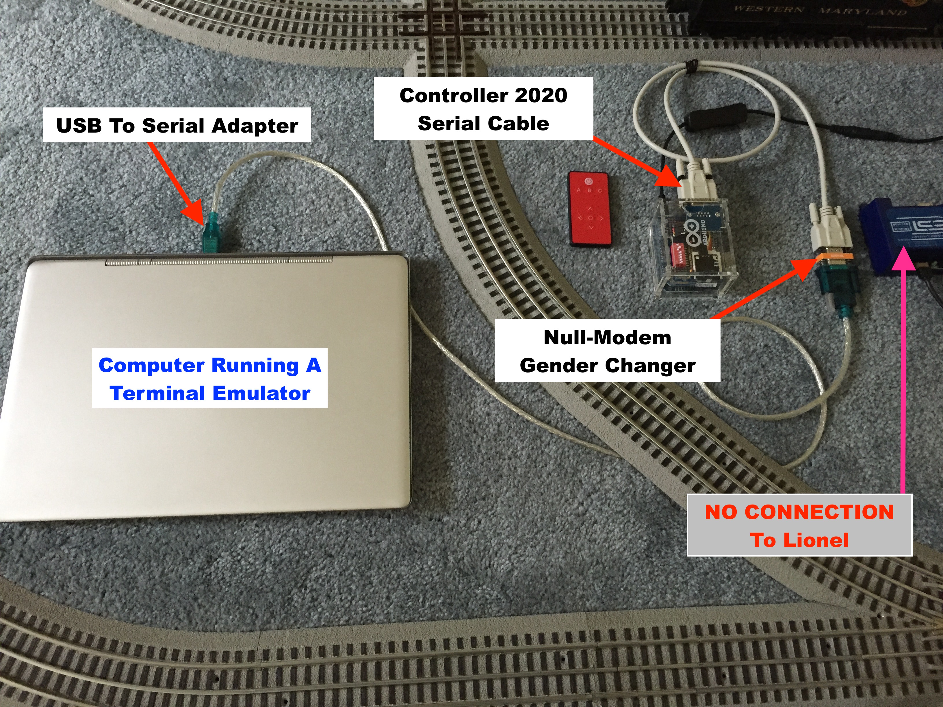
Figure 12. Debugging With The Controller 2020
Debugging Fun
Remember, the Controller 2020 must NOT be connected to the Lionel SER2. Some things you may enjoy debugging include:
Explore the inner workings of Soft Configuration. See software state transitions and Arduino
function calls with each press of an infrared remote key during the definition of a Soft Configuration.
Set dipswitch pins 3, 4, 6, and 8 ON with pins 1, 2, 5, and 7 OFF.
See the ASCII text version of the TMCC commands sent from the Controller 2020. Set dipswitch pins 6 and 8 ON, all others OFF.
See Grandkids Mode limiting the tops speed of an Engine. Set dipswitch pins 6, 7, and 8 ON, the others OFF.
Choose a Mode that controls an Engine and see how the top speed is limited.
Terminal Emulator Programs
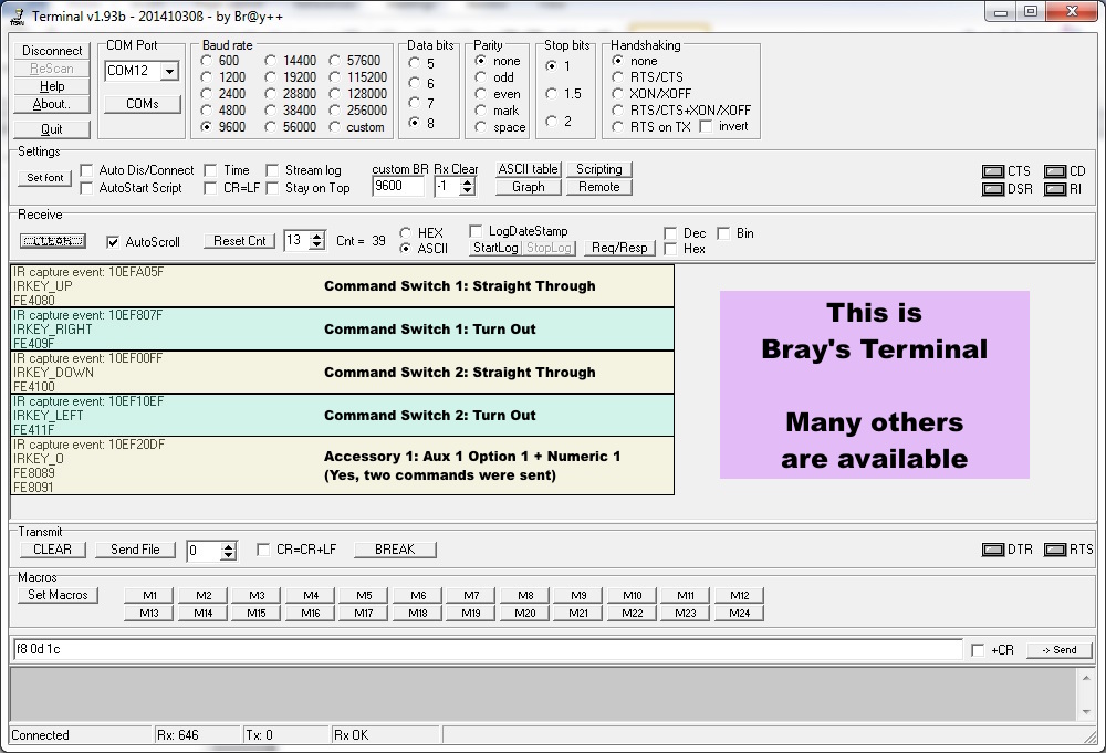
Figure-13 below shows a sample debugging session using Bray's terminal program (version 1.93b). A
large number of terminal emulation programs can be used instead. The Internet is your friend.
Do some research and pick one you like - of course being careful of the viruses, malware, and CIA
mind control lurking on the Internet.
Both the Controller 2020 and the PC implement the DTE (Data Terminal Equipment) side of the RS-232
serial connection. This means you need a "Null Modem" adapter and a Female-Female gender changer to
connect the Controller 2020 to your PC's serial port. Figure 12 above shows a Controller 2020/PC
connection using a combination gender changing null modem adapter (and a USB-to-serial adapter).
Construction Project 1: Automating Control of A Lionel Searchlight Car
The Electric RailRoad Company makes several command control receivers compatible with the
Lionel Legacy system. The following describes installing the Electric RailRoad Company
Mini Commander Acc
in a Lionel 6-36863 Alien Security (Searchlight) Car. The Lionel 6-36863 is similar to
other Lionel Searchlight cars.
I bought the Electric RailRoad Company Mini ACC Lionel "Hot Box" Car Kit which includes a wire harness,
double sided mounting tape, and an install guide. The guide was mostly useless for the searchlight car but the
Detailed Connection Guide
was very helpful. The "Hot Box" wire harness and mounting tape were used in the installation.
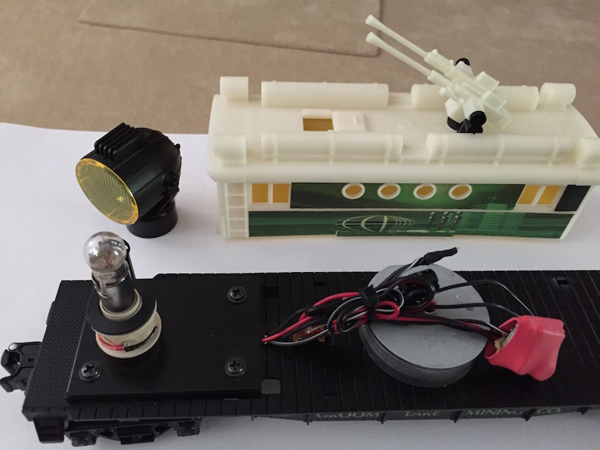
Figure CP1.1. The disassembled Lionel 6-36863
Before we actually take the car apart we want to put the searchlight lens in a safe place so we
don't drop it on the floor and step on it. It just lifts off to expose the lamp underneath. There
is a rubber gasket with little bumps on top that sits on the lamp base (it is not attached).
Small vibration of those little bumps is what makes the searchlight turn.
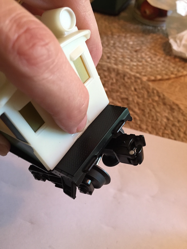
To disassemble the searchlight car, press the tab at the back of the car as shown in Figure CP1.2.
The tab is mostly hidden below the deck of the car but if you look closely you can see it.
While pressing the tab lift gently. This seems like a good time to mention that I offer no support
on this project and I am certainly not responsible if you hurt yourself or break something - so be careful.
This also seems like a good time to mention that you should read and make sure you understand the
programming instructions for the MiniCommander. The Electric RailRoad Company documentation
does a decent job of explaining this so I won't duplicate their effort. This article is about
installing the hardware in a car.
You will need:
Safety goggles, a soldering iron, solder, and some experience soldering.
Small pliers, wire/cable tie cutter, and a wire stripper.
Small sticky labels and a pen to label things as you work. I don't think it's a good idea
for you to make your labels the same as mine. You just want to make sure you can put everything
back together when you are done. Use labels that make sense to you.
Heat shrink tubing and a heat gun (or hold the tip of your soldering iron near the tubing to shrink it).
Maybe a couple of cable ties to make things look good.
Of course you also need a searchlight car and a Mini Commander...
...and don't forget to use proper anti-static precautions when working with electronics.
Figure CP1.2. Opening the Lionel 6-36863
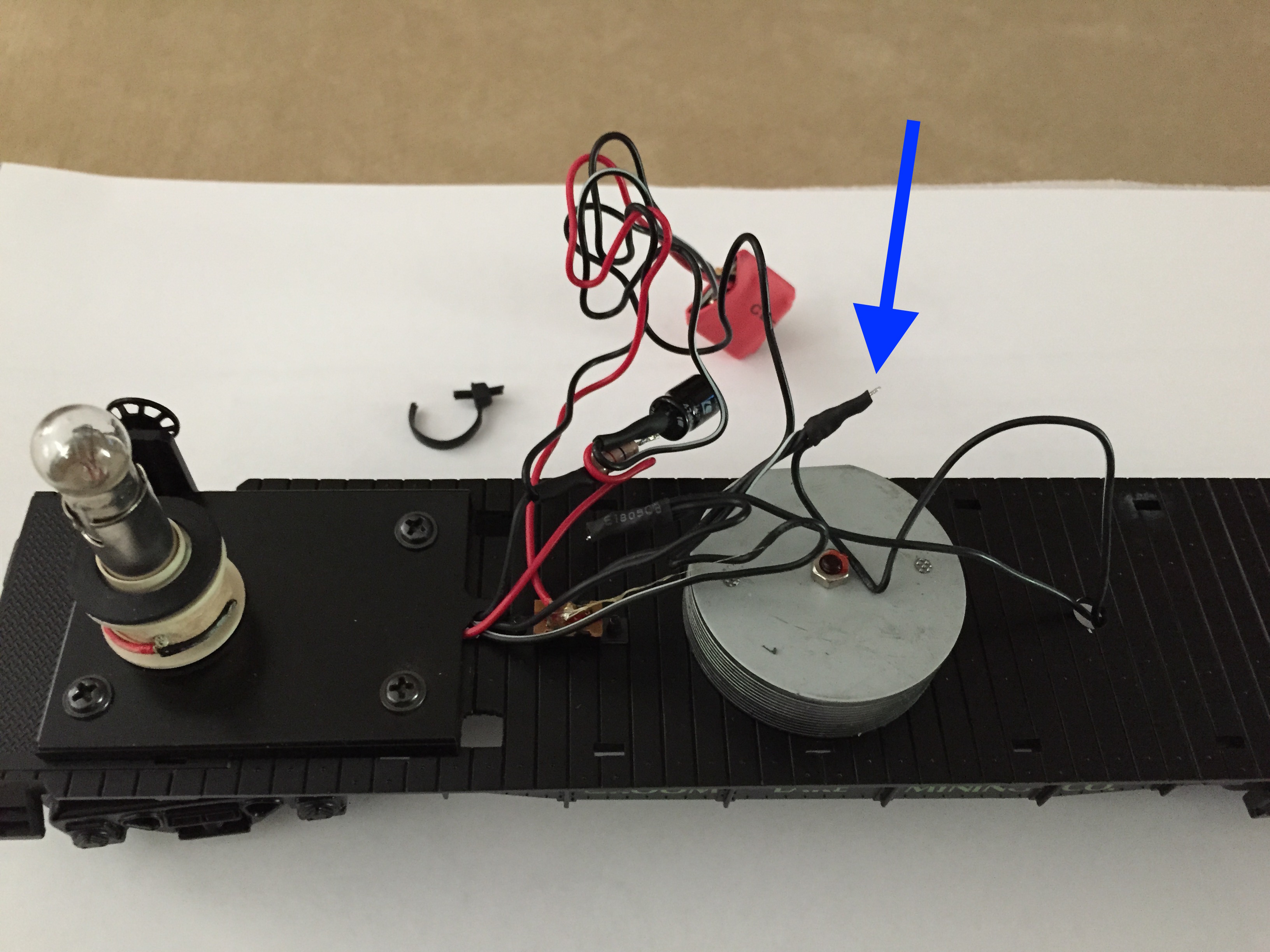
Begin by cutting the cable tie holding the wires. When we reassemble everything we will
use heat shrink tubing to cover exposed wires. Notice on the following picture (the blue
arrow) that the original assembly of this searchlight car left an electrical wire exposed
beyond the end of the heat shrink tubing. Yeah, don't do that. Make sure the wires are
completely covered to prevent electrical shorts.
A close look at the picture shows we have black wires, red wires, and black wires with a
white stripe. Black wires come from the wheels on both the left and right and black wires
with a white stipe come from the center rail roller on both sides. Notice that a red wire
also comes from the left. That actually goes to the lamp. In the picture you can see it
curl around from behind at the base of the lamp.
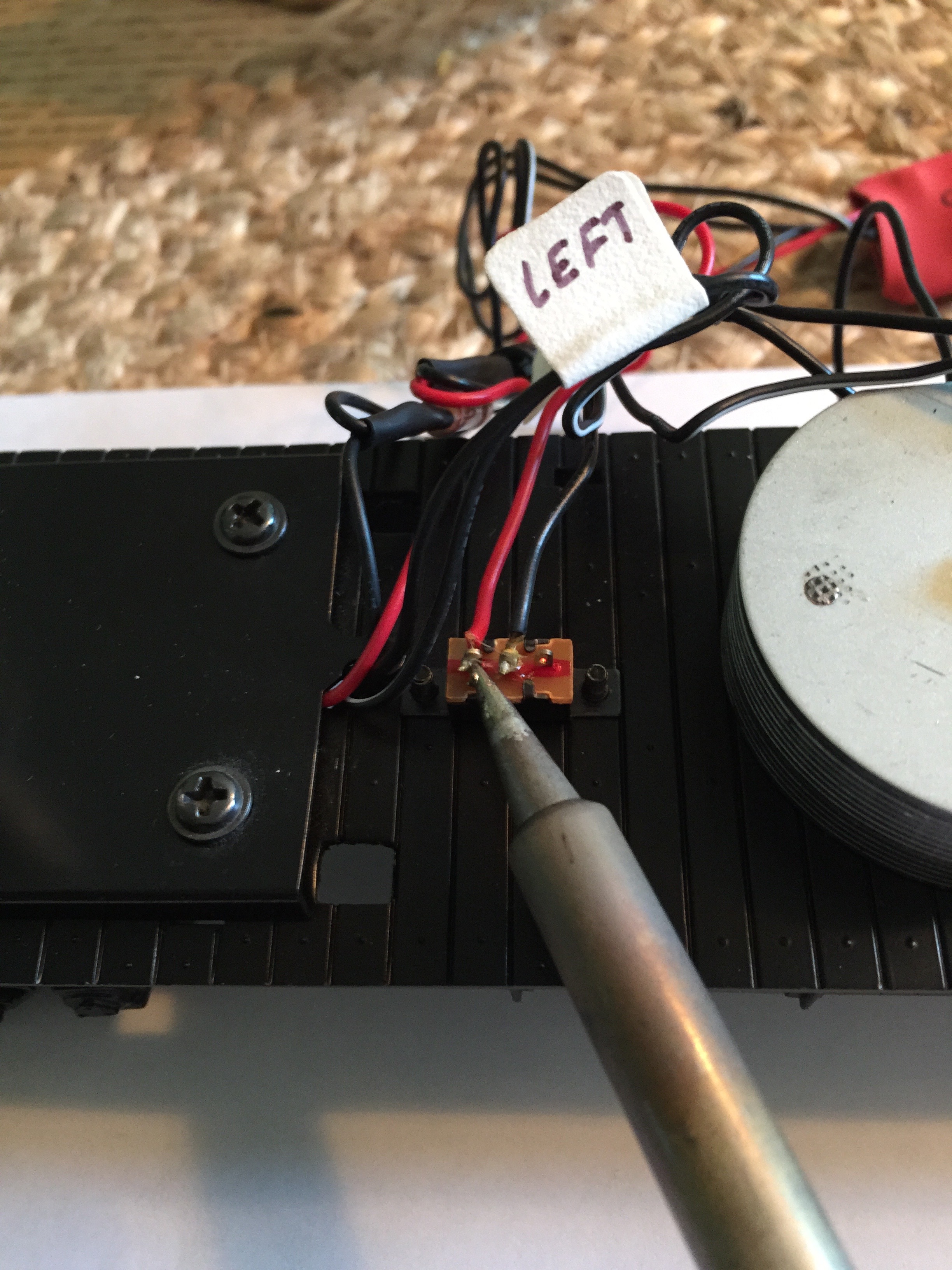
Figure CP1.3. Unbundling The Searchlight Wires
Find the switch that turns the searchlight on and off. It is to the left in all Figures in
this construction article. When we're done, the switch will no longer be used (but there is
no reason to remove it). The switch is electronically replaced by the MiniCommander.
Figure CP1.4. The Lionel Original 6-36863 On/Off Switch
There's a perfect open space to the right side of the car. Using the mounting tape from
the "Hot Box" kit, stick the MiniCommander to the train chassis. Make sure to leave room
to fit the top of the train back on the chassis. The connector side of the MiniCommander
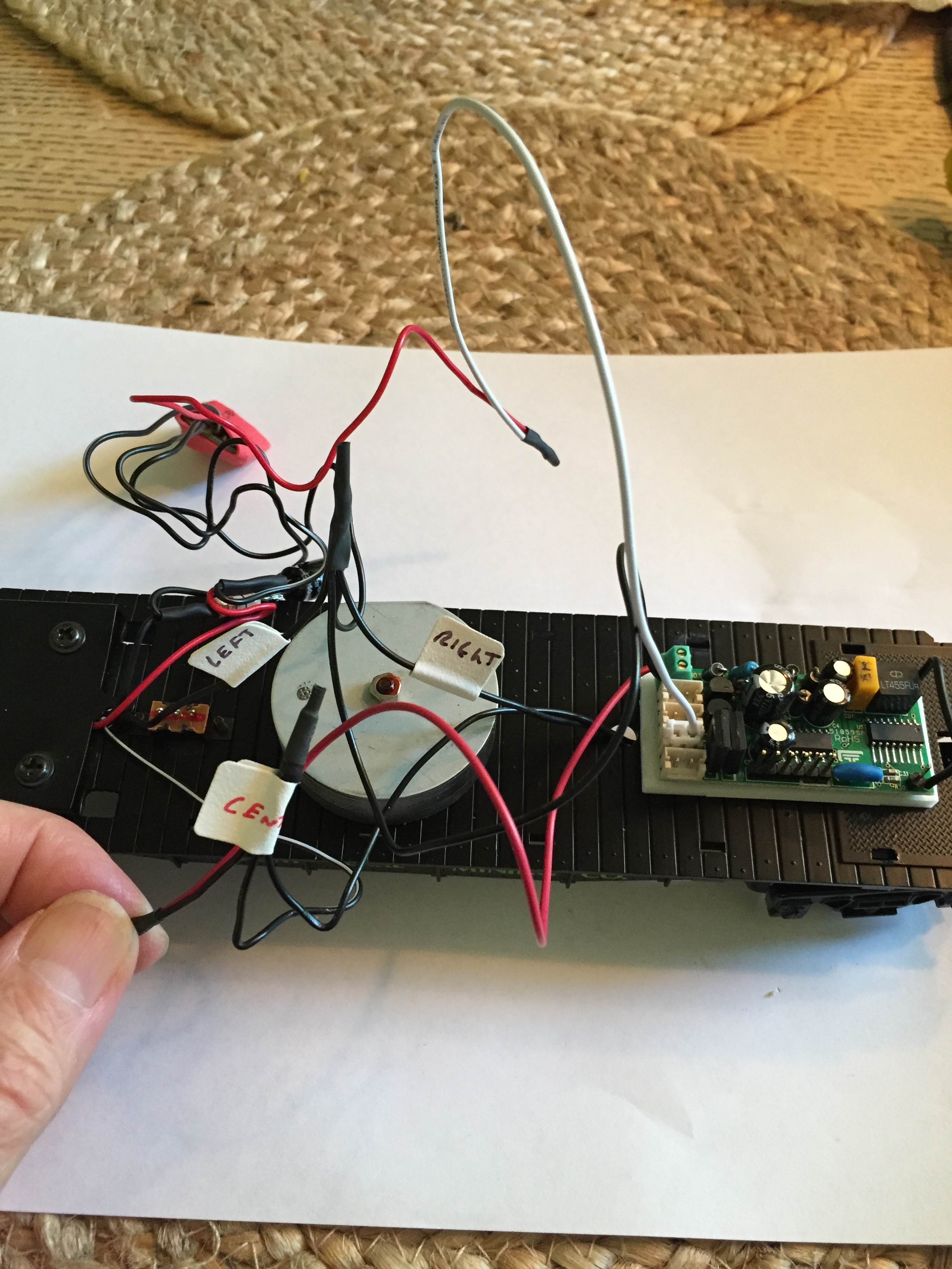
should be towards the center of the car. Your completed work should look like Figure CP1.6.
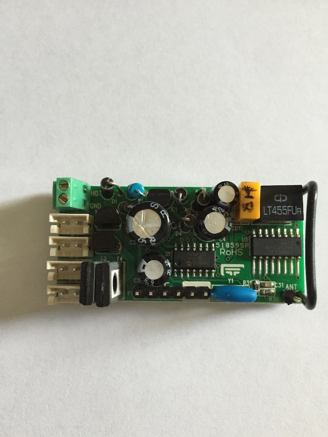
Figure CP1.5. The Electric RailRoad Company MiniCommander
The "Hot Box" kit comes with two white connectors - one of these connectors has two wires and
the other has one. For this application we want the connector with a single white wire. Set
it within easy reach.
I'm not sure all Lionel searchlight cars use the same color wires so please reference Figures CP1.3
and CP1.6 for this discussion. In CP1.3 you see a red wire on the left side of the switch that goes to the
little module shrouded in red heat shrink. Remove this wire from the switch. After removing it, cut off
the old end of the wire that was soldered to the switch and strip it to give it a nice clean look. Twist
it together with the end of the single white wire connector we set within easy reach above. Solder the
wires and cover them with heat shrink tubing. A good view of this can be seen in Figure CP1.6 where the
connector has been pressed into the second from bottom socket. This is the HC-1 socket on the MiniCommander.
You will program the MiniCommander to control the searchlight with the HC-1 socket.
The MiniCommander needs power and you provide that by connecting wires to the green terminal block at
the top left edge of the board as it is pictured in Figures CP1.5 and CP1.6.
The green terminal block has two screws. If you look carefully at the board, or the Detailed Connection
Guide, you will see the screw closest to the top edge of the board is labeled HOT and the other is labeled
GND. We will connect power to the terminal block using the wires included in the Hot Box kit. The Hot Box
kit pictured on the Electric RailRoad Company web site shows white and black wires but mine came with red
and black wires - whatever. It doesn't make any difference.
Solid black wires from the left and right wheels come together in a little bundle with a third black wire
under some black heat shrink. Carefully remove that black heat shrink. You can follow the third black wire
to the red heat shrink covered little module. Twist the Hot Box black wire together in the little bundle of
the other three wires and solder it. You now have a bundle of four black wires - this is the car's ground
circuit. Cover the exposed wires with some heat shrink. You can see the completed four wire bundle in the
center of Figure CP1.6.
We're almost finished. Unsolder the wire from the center of the switch. If you follow this wire you will
find it goes to the heat shrink bundle where the black wires with the white stripe come together. Cut off
the old soldered end and strip the wire to give it a nice clean look like we did with the other wire we
unsoldered from the switch. Twist this wire together with the red
wire from the Hot Box kit. Solder it and cover it with heat shrink. Put the other end of the red
wire in the HOT hole of the MiniCommander's green terminal block. Put the free end of the Hot Box kit black
wire in the GND hole of the terminal block. We should be done, but before putting the top of the car back on,
program and test your work on your Lionel Legacy System.
Put a cable tie or two on the wires to keep them out of the way - but make sure to leave enough slack in the wires
for the wheels to turn.
Note: If your Hot Box kit came with black and white wires, replace the underlined word red above with "white".
Make sure everything clears - then snap the top of the car back in place and put the searchlight lens
back on.
Enjoy your very cool remote controlled searchlight.
Construction Project 2: Assembling The Controller 2020 Kit
The Controller 2020 is available for purchase as a kit
and this section describes how to assemble it.
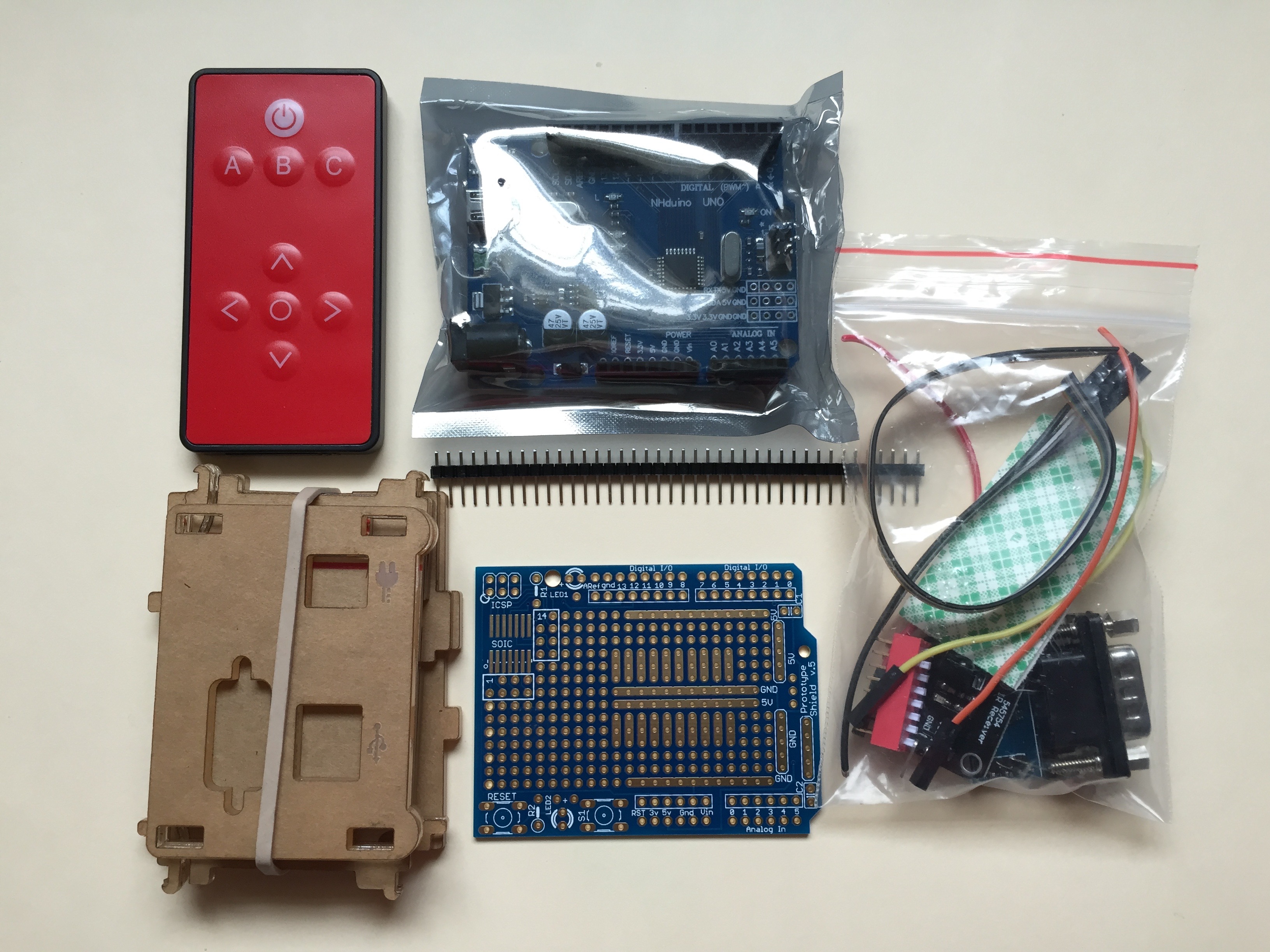
Figure CP2.1. The Controller 2020 Kit
Before starting, gather the following:
Safety goggles, bandages, food, and refreshments
Soldering iron, solder, small pliers, wire stripper, and a circuit board holder. The circuit board
holder could be replaced by an occasional human assistant.
The Controller 2020 Kit
...and always use proper anti-static precautions when working with electronics.
The Controller 2020 Kit contains (note that the brands and colors may vary):
An Infrared Remote with a CR2025 battery included.
One enclosure, (6 sides, unassembled).
Motherboard (Arduino UNO or clone).
Proto Shield blank board with a 40 pin strip.
A bag of parts - What's in the bag?
5 or 6 inches of 8 conductor ribbon cable (to connect to the dipswitch).
A few inches of 4 conductor ribbon cable with connectors on one end.
This is to connect to the RS232 interface.
Three different color wires, a few inches long, with connectors on one end.
These are to connect to the IR receiver.
One IR receiver.
One IR receiver plastic mount.
Two 1 inch squares of mounting foam.
One RS232 board with a DB9 male connector. This connector comes with two 18mm (nominal)
UNC Jack Post screws and washers. Note that the length of these may vary from kit to kit.
One eight position dipswitch (16 pins, 8 switches).
Two capacitors, one smaller than the other.
This is not an especially difficult kit to assemble, but it should probably not be the first time
you do something like this. There is no "right" sequence to assembling the Controller 2020 kit but
I found the following works.
Peel the protective paper off the clear acrylic enclosure and assemble it. Do this before
you warm up the soldering iron since peeling the paper off can be a challenge for those
with uncooperative fingernails. The assembled enclosure should look like Figure CP2.2.
Set it in front of you while you work on the circuit board so you can to imagine how cool
your toy will be when you've completed it.
Note: Only one enclosure comes with the Controller 2020 kit. For clarity Figure CP2.2 shows two
enclosures - one from the end and another from the side - but you only get one enclosure.
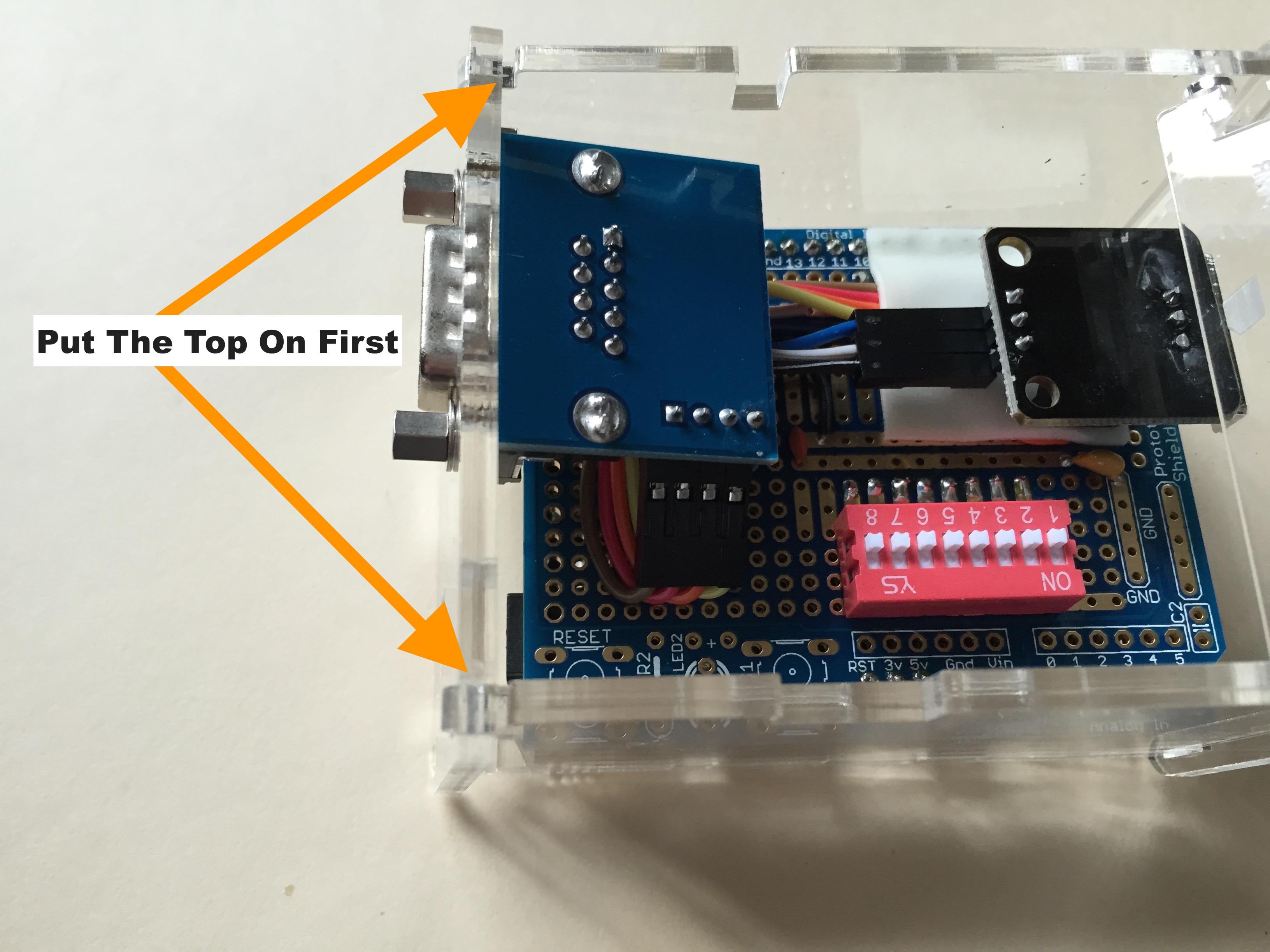
Also Note: Assemble the enclosure by first standing up the sides and pushing them together on
the bottom. Insert the lid hinges in the holes in the sides. Make sure the tabs on the lid
align with the sides as shown in Figure CP2.2. Loop the front panel, the one with the IR receiver
window, over the catches at the top. Make sure you put the top on first - then (gently) compress
the springy catches on the bottom, align the panel, and it should snap lightly in place. Repeat
this process with the back panel - top first, compress springy things on the bottom, lightly
snap in place. The acrylic is sturdy but it will break if you press too hard. NO PART OF THIS
ASSEMBLY REQUIRES FORCE. If you find yourself pressing hard on something, put it down and walk
away for a few minutes.
Solder the strips of pins to the bottom of the board.
Solder the ribbon cable to the bottom of the board. Doing this before anything
is mounted on the top of the board allows it to lay flat while you struggle with
the wires.
Solder the dipswitch to the top of the Proto Shield.
Solder to the top of the Proto Shield the EMI reduction caps and the wires that connect
the infrared receiver and the RS232 connector boards.
Attach the infrared receiver plastic mount to the Proto Shield with a full 1 inch square
of mounting foam. This mounting foam is also partially applied over the previously soldered wires.
It serves as a strain relief to hold the wires in place and prevent excessive flexing of them when
you push their connectors onto the IR receiver and RS232 boards.
Note: The factory assembled Controller 2020 solders the wires to the IR receiver so they don't
shake off during shipping. In the comfort of your home you don't need to solder the connectors.
Pushing them on is fine.
Attach the infrared receiver to the top of the plastic mount with a piece of mounting foam.
Remove the back panel from the assembled acrylic enclosure. Remember, this case is plastic -
a sturdy plastic that looks very cool, but plastic. It will scratch and will break if
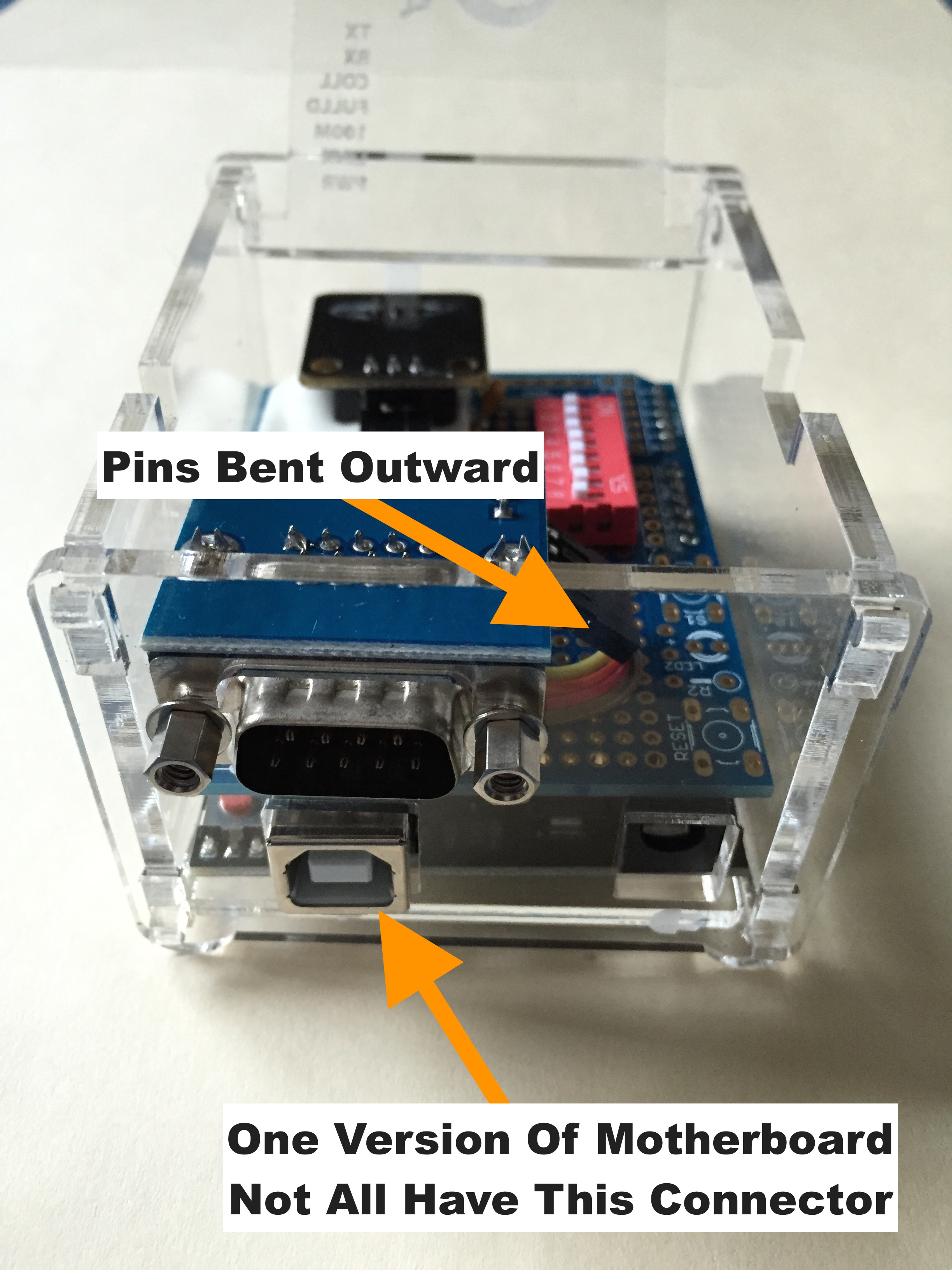
you go gorilla on it. Attach the RS-232 connector to the back panel with the washers on the
outside between the UNC Jack Post screws and the acrylic. Later, you will push the connectors
of the 4 conductor ribbon cable onto the RS232 board pins. You need to bend the four pins
outward to about 45 degrees so the connectors clear the Proto Shield when everything is assembled.
You want to use a small pair of pliers to bend them at the top of the plastic, not at the circuit
board. Bending them with your thumb at the circuit board may fracture the solder joint.
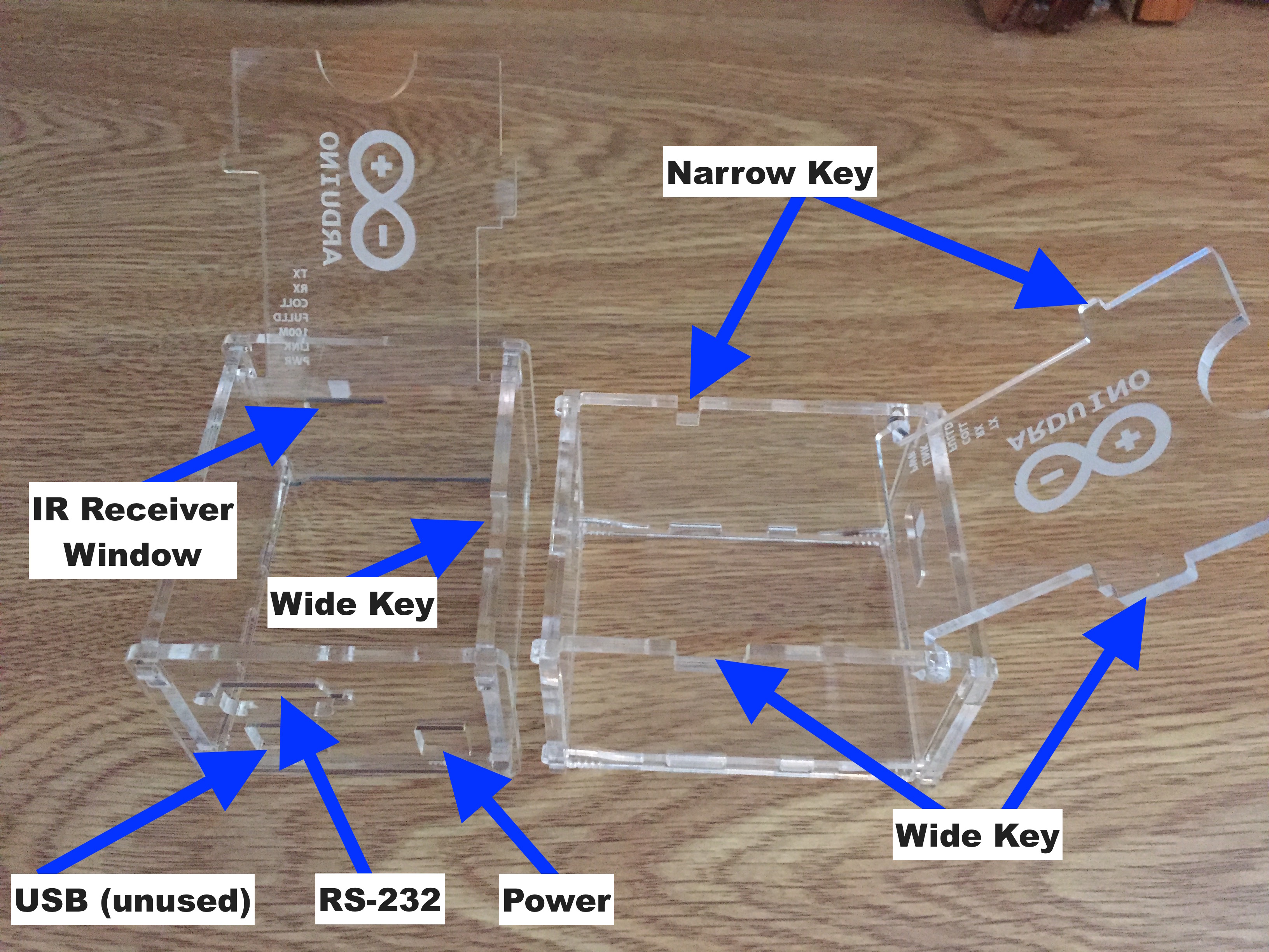
Figure CP2.2. The Acrylic Enclosure
There are two Proto Shields in Figure CP2.3, one of the boards shows its top side and the other
shows the bottom.
Note: This is done for clarity - you only get one board in the kit. You do, however, get
the entire 40 pin strip.
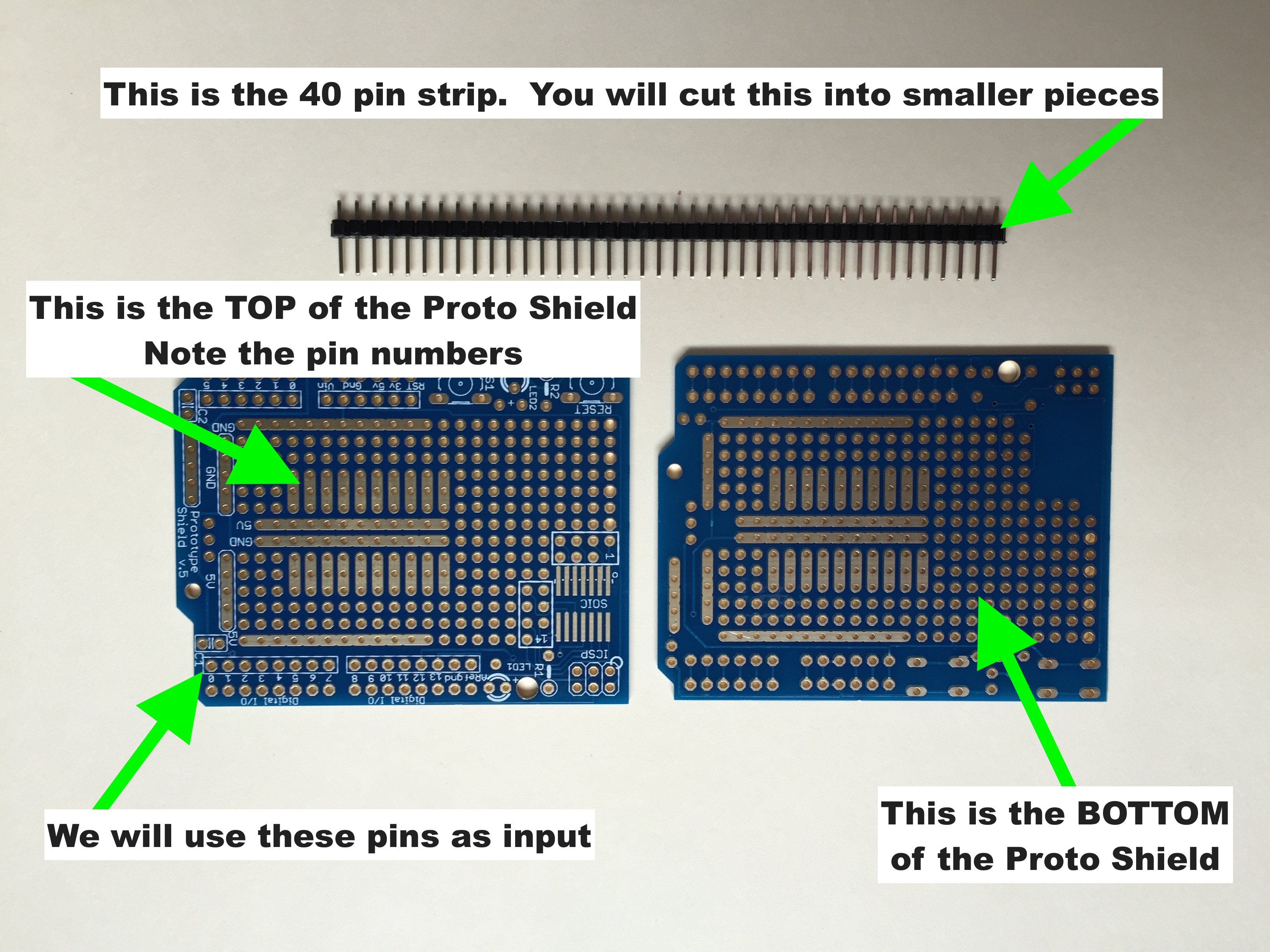
Figure CP2.3. The Bare Proto Shield With 40 Pin Strip
Detailed Instructions
As shown in Figure CP2.4, the provided 40 pin strip of pins must be cut into two 6 pin strips
and two 8 pin strips. You can toss the remaining 12 pin strip in your junk box for a future project.
Solder the pins so they stick out of the bottom of the board. The pin numbers are printed on
the top of the board. No pin numbers are visible on the side from which the pins project.
You want the pins as perpendicular as possible - for final assembly you will align these pins and
press them carefully into the provided motherboard. Do not press the pins into the motherboard
and use that to hold them in place while you solder. The soldering heat may damage the motherboard connector.
Figure CP2.4. The Proto Shield With Cut Pins
Look at Figure CP2.6 and Figure CP2.7 to make sure you solder the pins in the right place.
When finished, strip and tin one end of the 8-conductor ribbon cable as shown in Figure CP2.5.
There are no connectors on this ribbon cable.
Figure CP2.5. Prepare The Ribbon Cable For Soldering
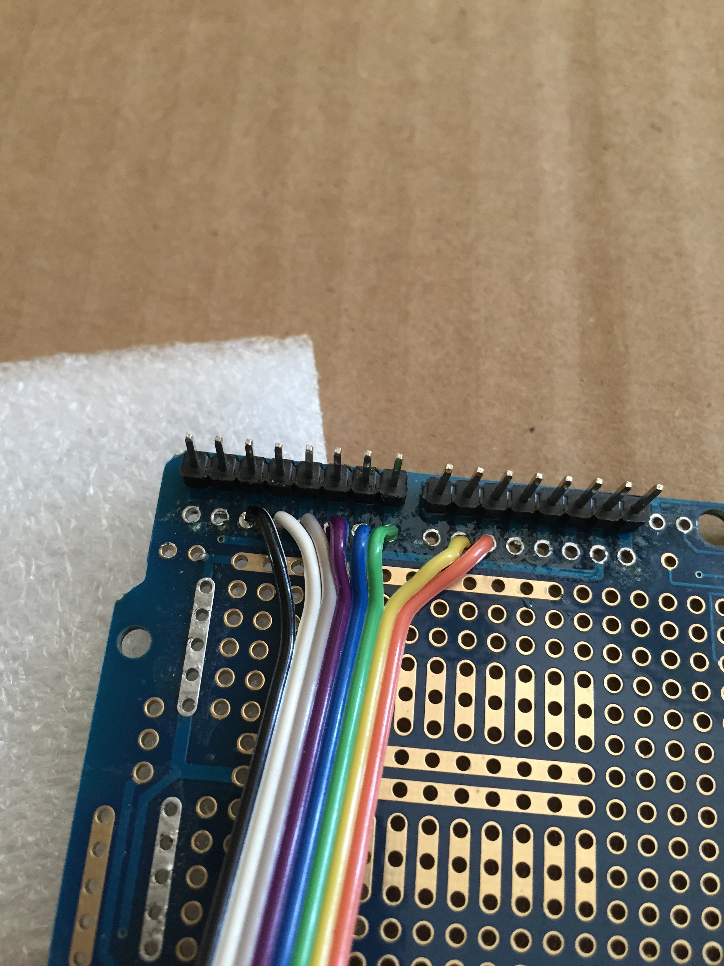
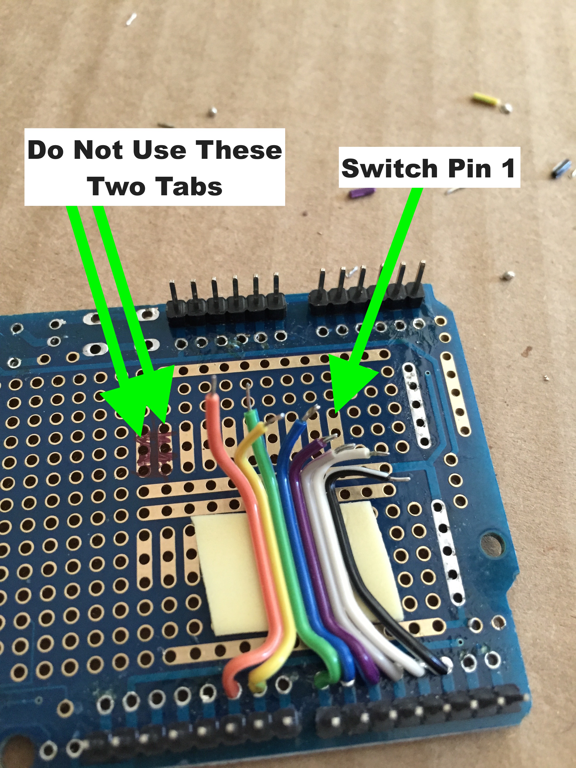
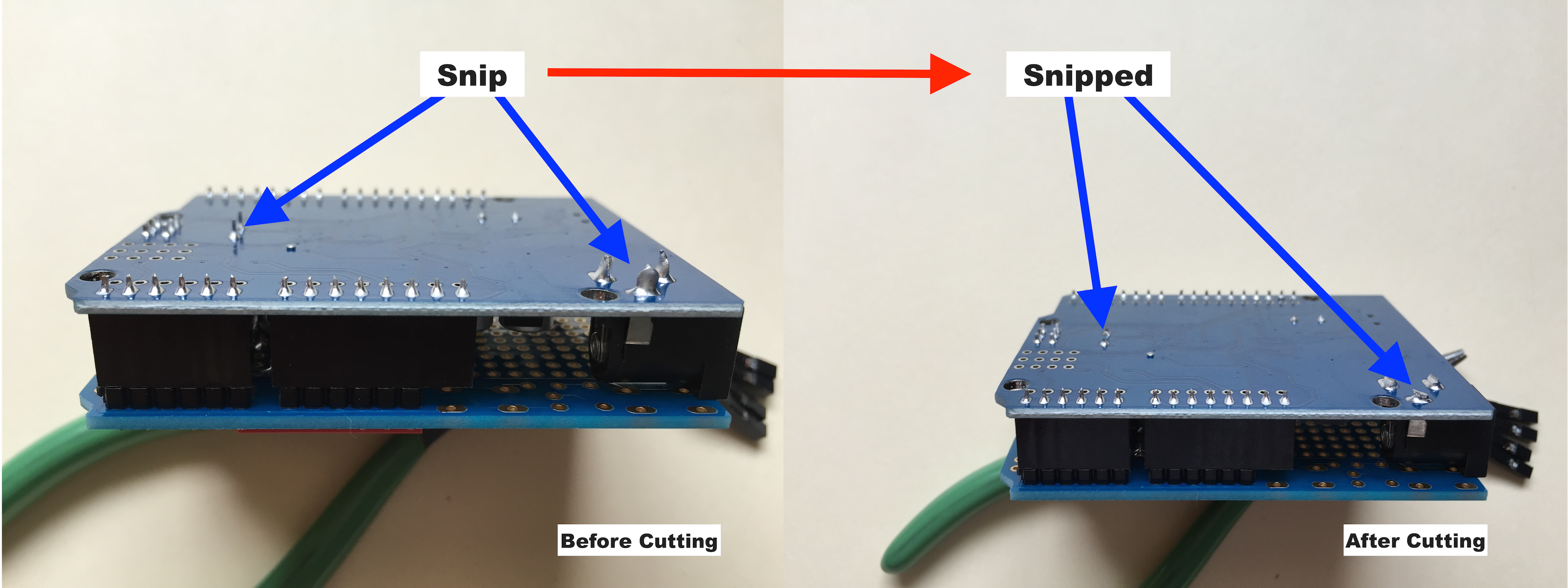
The Proto Shield pins are counted from zero and pin 0 is shown to the left in Figure CP2.6 below.
The actual colors of the wires are not important and may vary from kit to kit. The ribbon cable
in the picture shows the black wire connected to pin 2 and the orange wire connected to pin 10.
The ribbon cable is not connected to pin 8
Cut the ribbon cable approximately in half. The kit provides enough cable for two
tries at soldering in case something goes wrong the first time. We will solder the eight wires
of the cable to the Arduino digital input/output (I/O) pins. Start with one edge of the ribbon
cable and solder the first wire to pin 2 (counting from 0), the next to pin 3 and so on until
pin 8. Skip over pin 8 and solder the seventh wire to pin 9 and the eighth to pin 10. Remember,
the numbers are printed on the top of the board and the ribbon cable goes on the bottom. Your
work should look like Figure CP2.6 when finished with the first end of the ribbon cable.
Figure CP2.6. Bottom of The Circuit Board With Pins And Ribbon Cable
With one end of the ribbon cable installed, cut a small piece of the double-sided mounting foam
and use it to hold the cable in place. This prevents flexing the solder joints while you work
on the other end of the cable. Prepare the second side of the cable by carefully
estimating the needed length and cutting it. If you cut it too short you'll have to unsolder the
first side and try again. It can be hard to solder the cable the second time since solder may
remain in the holes after you remove the old cable (experienced builders will have the tools to
handle this but an experienced builder probably wouldn't have cut the cable too short).
Strip and tin the second end of the cable as shown in Figure CP2.7.
Figure CP2.7. Prepare The Ribbon Cable - Again
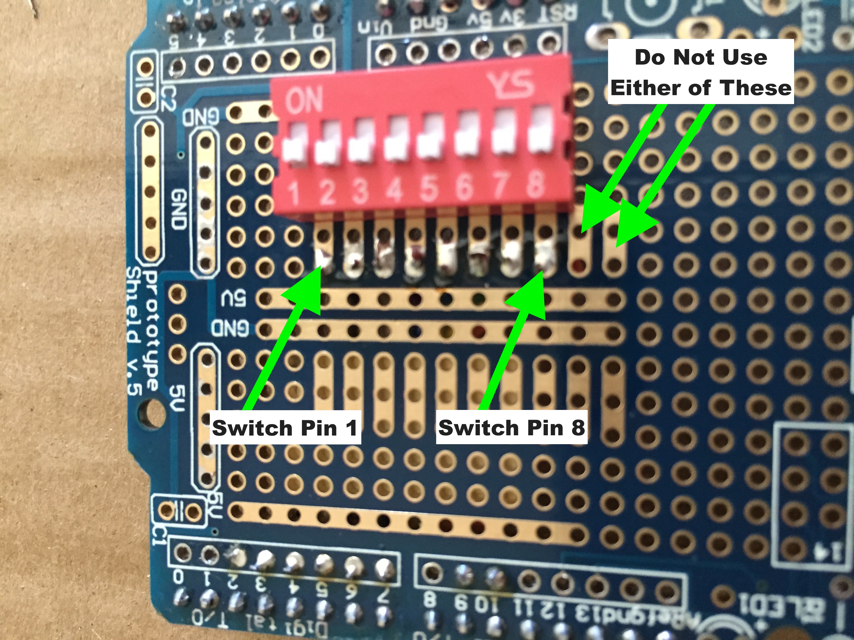
After soldering the ribbon cable install the dipswitch on the top of the Proto Shield. Be
careful to orient it as shown in Figure CP2.8.
Note: Very Important all 8 pins on the numbered side of the dipswitch
must be in the pads used by the ribbon cable. This will leave two solder pads open as shown
in Figure CP2.8.
Also note: Very Important the pins on the other side of the dipswitch must
go in the trace labeled GND.
Technical Information: The Arduino digital pins connected to the dipswitch are configured as inputs
with internal pull-ups. When a pin of the dipswitch is moved to the ON position it grounds the
pull-up and the value read from the Arduino input pins changes from 1 to 0. This is how the configuration
setting is read at power up.
Figure CP2.8. Top of The Circuit Board With The Switch Installed
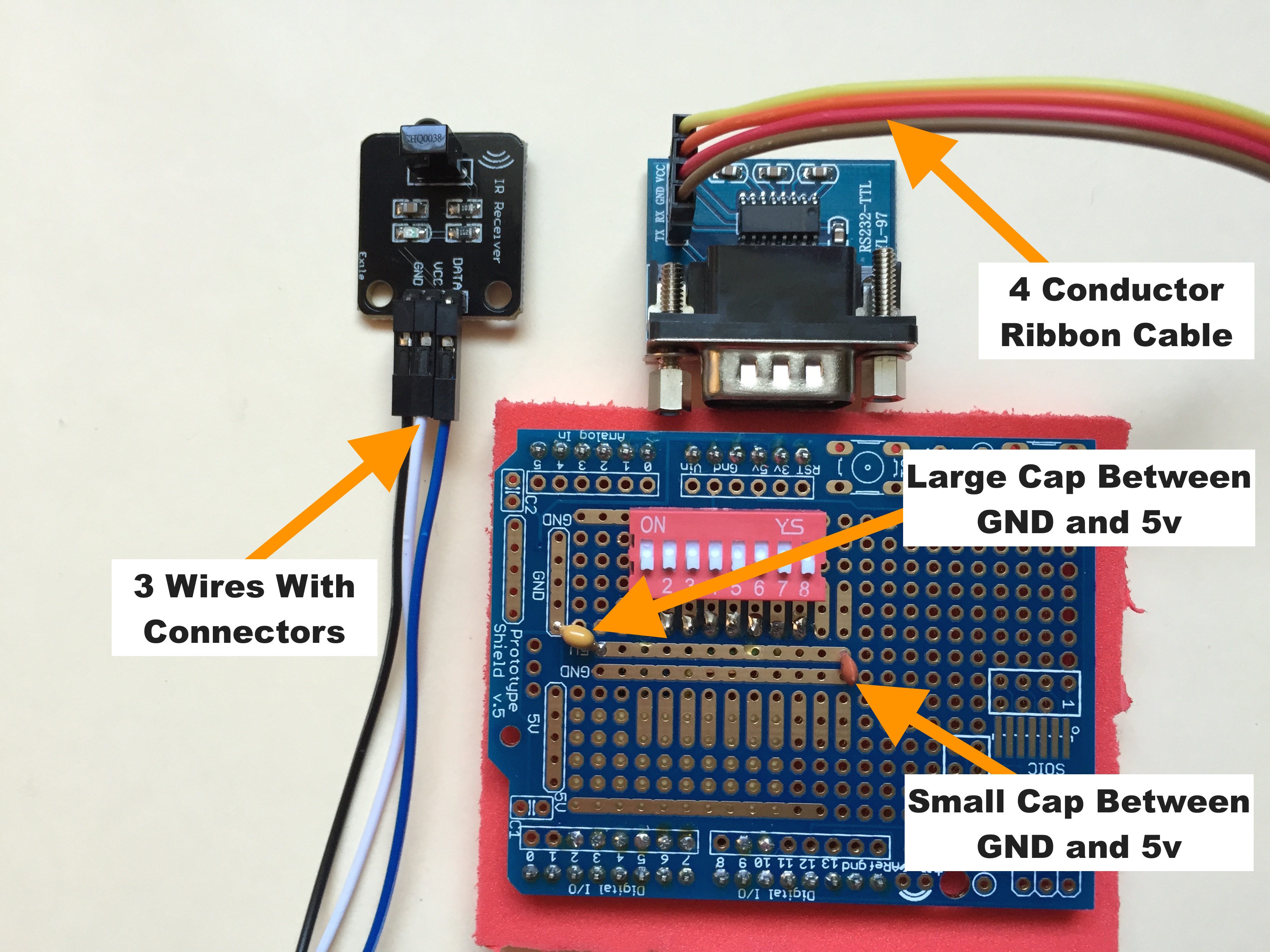
With the Arduino pins, ribbon cable, and dipswitch in place it is now time to install the FCC capacitors
and the wiring for the IR receiver and RS232 interface. All of this goes on the top of the Proto Shield
with the dipswitch. I recommend the capacitors to reduce the FCC ElectroMagnetic Interference (EMI) of
the Controller 2020. Although not FCC certified, smart people with expensive equipment did take a look
at the Controller 2020. It was pretty clean but these caps made it even better. Solder the bigger cap
near pin 1 of the dipswitch as show in Figure CP2.9. Be careful with the placement and make sure you
get one leg of the cap in 5v and the other in GND. Solder the small one at the bottom of the parallel
GND and 5v strips as also shown Figure CP2.9.
Figure CP2.9. Install The EMI Reduction Caps
Two ribbon cables are included in this kit. You already used the one with 8 wires. There is also one
with 4 wires and it has connectors on one end. We will use the 4 wire ribbon cable to connect the
RS232 board to the Proto Shield. Finally, the kit has three wires (not ribbon) with connectors on
one end. These are used to connect the IR receiver.
The three non-ribbon cable wires are different colors. The actual colors don't matter and may vary from
kit to kit. Eventually, not yet, you will push the three connectors onto the three pins of the infrared
receiver board. Look at the bottom of the little IR receiver circuit board and notice that one of the pins
has a square eyelet. A square eyelet traditionally indicates pin one (1). Flip the little board over and
notice that this pin 1 is labeled DATA (on some boards this is 'DAT'). Pin 2 next to it is labeled VCC and
pin 3 is GND. Pick a color to use for pin 1 - let's say that is color-D. Now pick the color-V
wire that goes to VCC and the color-G wire that goes to the GND pin. Obviously there are no such colors
as color-D, color-V, and color-G. The point is the actual color doesn't matter. What's important is that the
wires connect the correct IR receiver pins to the correct Proto Shield pins.
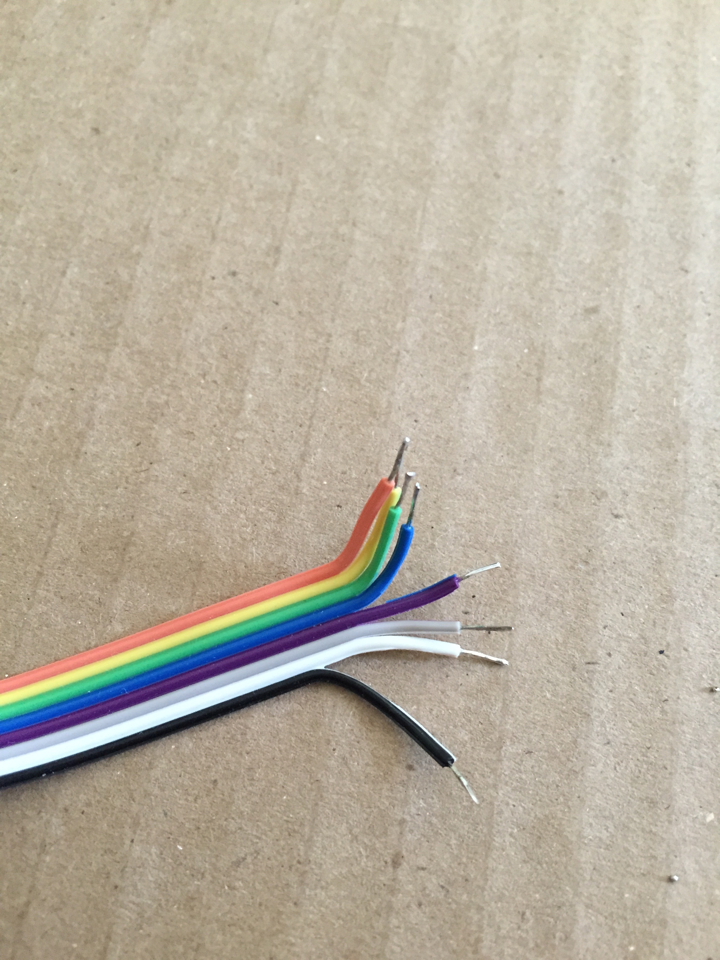
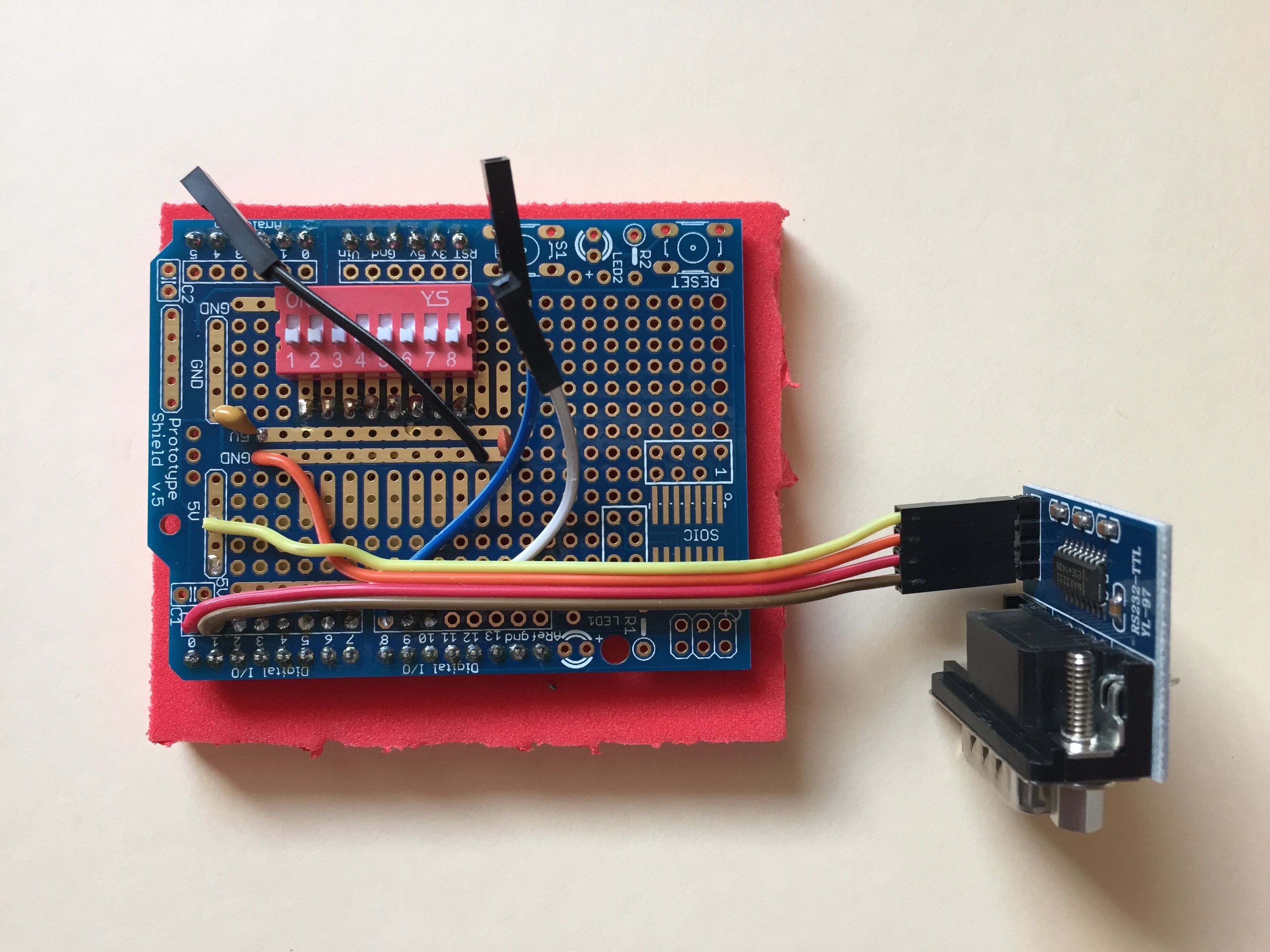
Look at your Proto Shield and Figures CP2.10 and CP2.14 and estimate the needed length of the three infrared
receiver wires. For each wire cut the end of the wire opposite the connector appropriately, then strip and
tin the end. Figure CP2.13 shows how the wires might be cut.
Remember, it's better a wire be a little too long than it be too short. For example, as can be seen in
Figures CP2.10 through CP2.14, the black IR receiver wire could be a little shorter but the extra length
causes no problem.
Solder the color-D wire (blue in Figure CP2.10) to Proto Shield pin 8 - that's the one we skipped over
when we soldered the first ribbon cable. Be careful not to melt any of the ribbon cable while working
in the close quarters. Solder the color-V wire (white in Figure CP2.10) to a convenient 5v area on the
Proto Shield and solder the color-G wire (black in Figure CP2.10) to a GND strip. When finished you work
should look like Figure CP2.10 - of course your wires may be different colors.
Oh - you should have been observing proper anti-static precautions while handling these boards. I hope you were.
Now strip and tin the non-connector ends of the 4 conductor ribbon cable. Do not shorten this cable. We want
it full length to reach across the board to the mounted RS232 connector. Pin 1 on the little RS232 board (also
with a square eyelet) is labeled TX, pin 2 is RX, 3 is GND and 4 is VCC. Decide which edge of the ribbon cable
you want to connect to pin one. We will call that wire color-T. The next wire on the ribbon is color-R
and that goes to pin 2, then color-G goes to pin 3, and color-V on the other edge of the cable will be
connected to RS232 pin 4. Solder the non-connector end of color-T to pin 1 of the Proto Shield and the
color-R wire to pin 0 (yes, RS232 pin 1 to Proto Shield pin 0 and RS232 pin 2 to Proto Shield pin 1). Color-G goes
to GND and color-V goes to 5v on the Proto Shield as shown in Figure CP2.10. Notice the positioning of the color-G
(orange) wire that goes to the RS232 board. It has a little curve in it to clear the leg of the plastic IR receiver
mount as shown in Figure CP2.11.
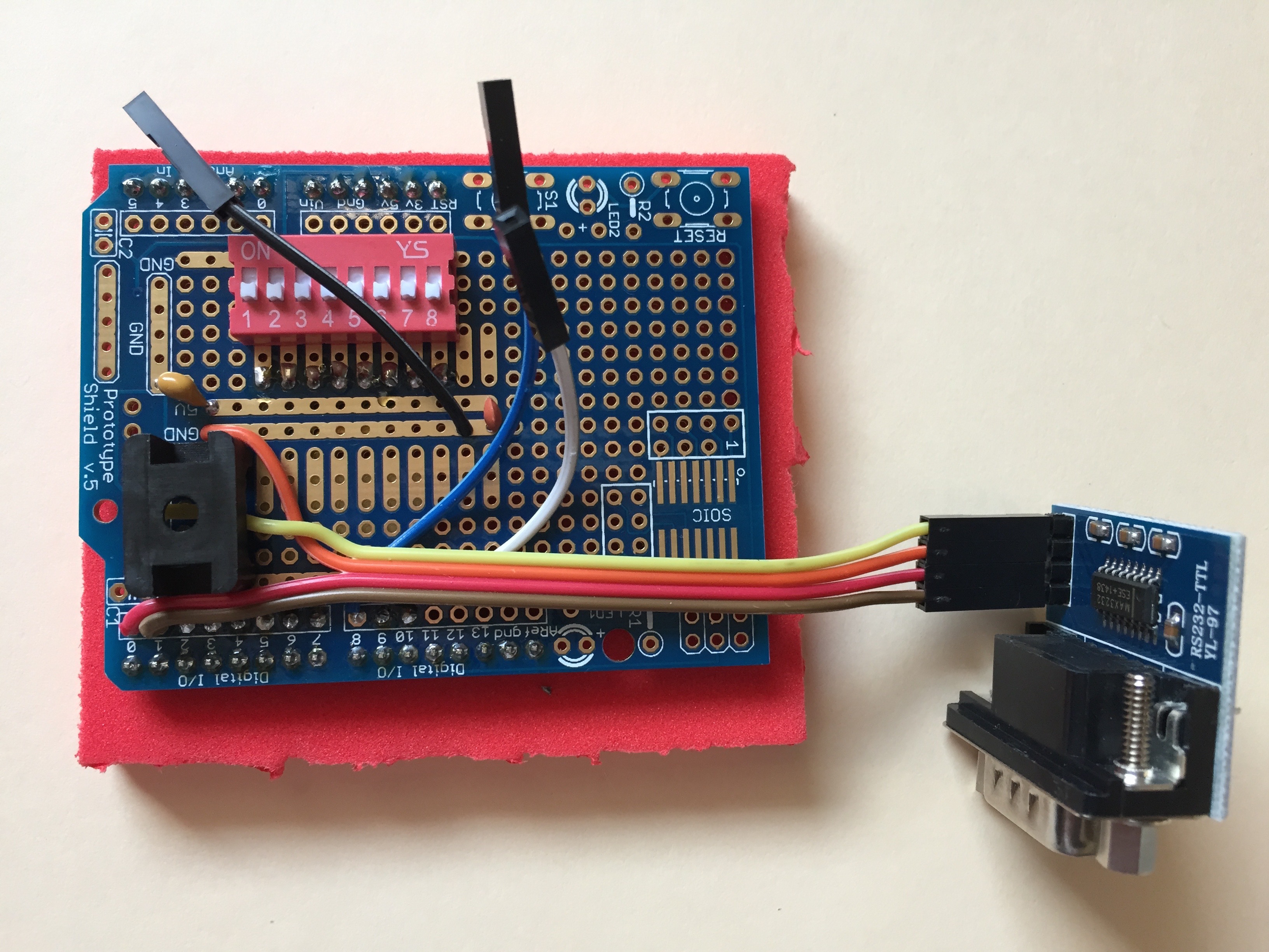
Figure CP2.10. Placement of The IR Receiver And RS232 Wires
We are finished soldering. You can turn off the soldering iron.
Attach the plastic mount for the IR receiver to the Proto Shield with a full one inch square of mounting
foam as shown in Figure CP2.12. Notice that the mounting foam is back from the edge and even with the
front of the circuit board pad labeled 5v and extends beyond the side of the plastic mount on top of the
soldered wires. The bridge side of the plastic mount goes down on the Proto Shield. Exact placement of
the plastic mount is important but not critical. You can be off a little and the Controller 2020 will
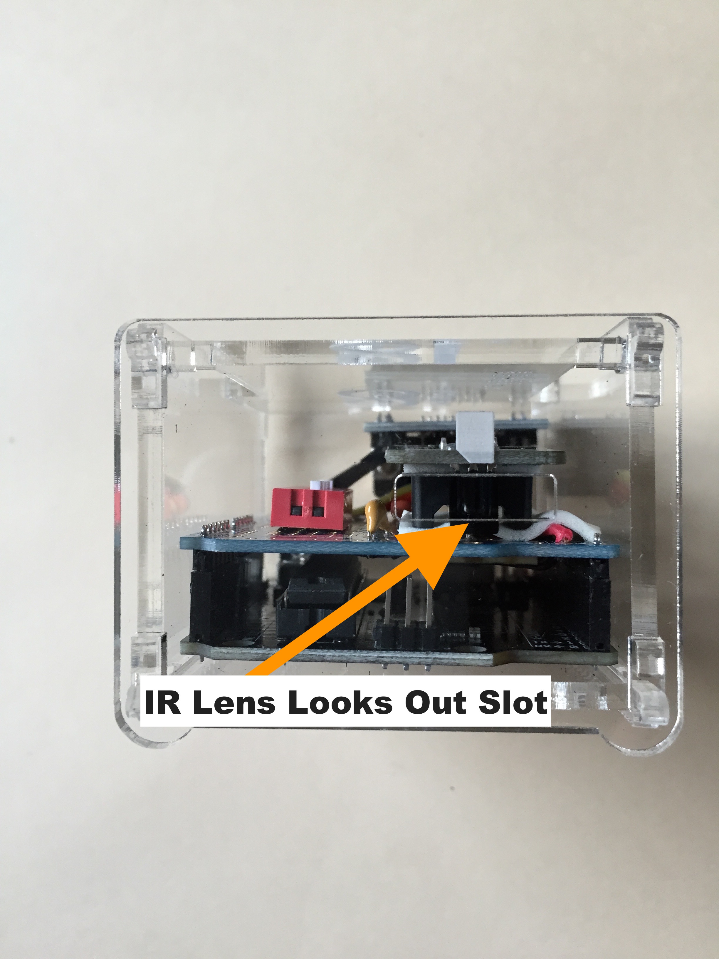
still work. When well positioned the lens of the mounted infrared receiver will look through the small
window in the front of the enclosure as shown in Figure CP2.21.
Figure CP2.11. Wires Around And Under The IR Mount
Peal off the bottom of a 1" square of mounting foam and stick it to the board as shown - even with
the front of the 5v pad and across the wires. You want the wires held in place so the plastic mount
clears the wires and can touch the Proto Shield through the thickness of the mounting foam. You
don't want the legs of the plastic mount sitting on top of a wire. One wire goes through the legs
of the mount, one goes to the dipswitch side, and the others go to the other side. Leave the
protective top sheet on the foam and squeeze the foam down onto the Proto Shield. Don't break
anything but squeeze it pretty hard to really stick it to the board, holding the wires in place.
Now remove the protective top sheet, align the plastic mount, and push down hard on the mount to
make sure it gets stuck to the board. Don't break anything!
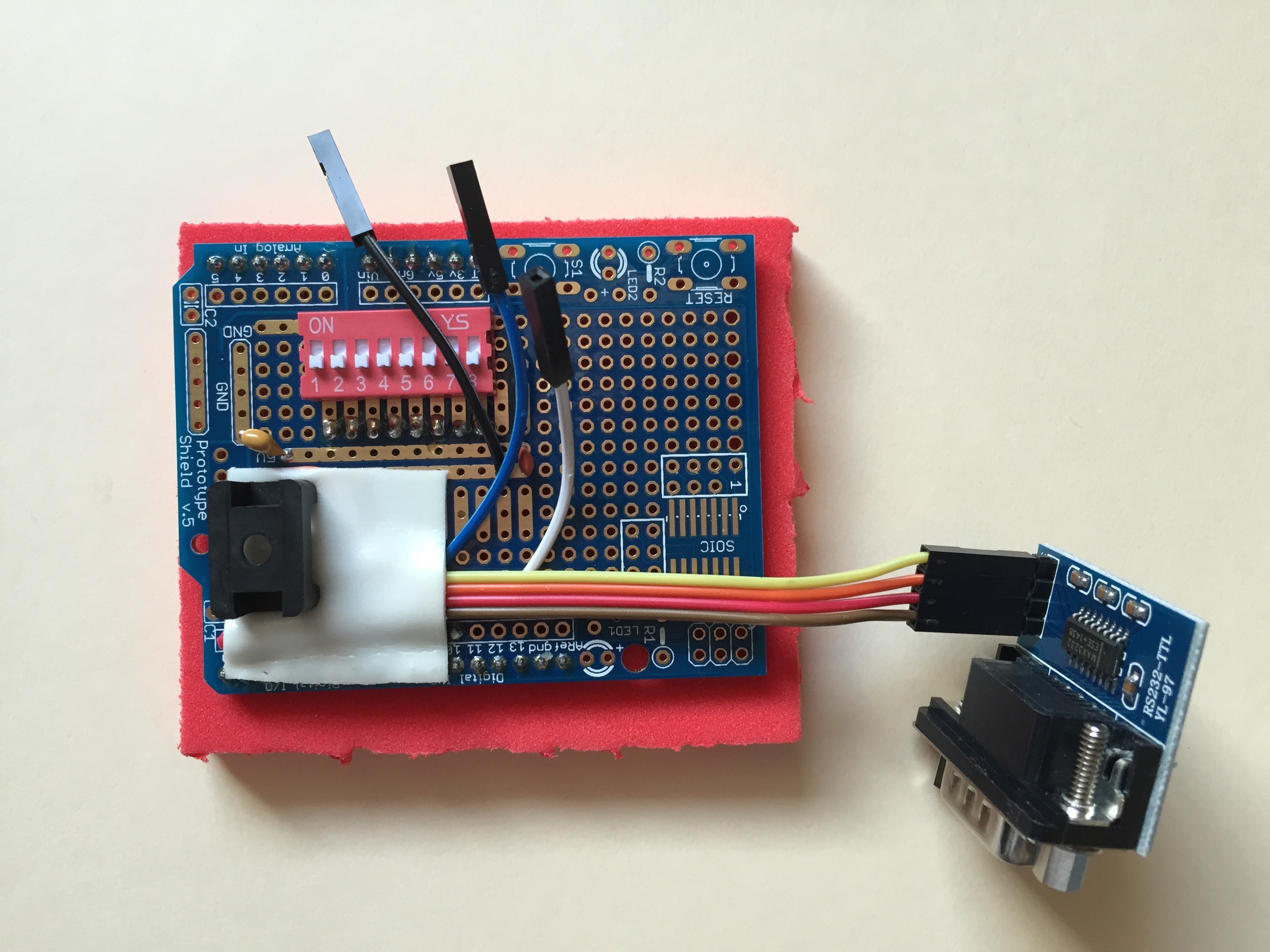
Figure CP2.12. Placement of The Mounting Foam
Cut a piece of mounting foam the size of the top of the IR receiver plastic mount and
stick it on top of the mount as shown in Figure CP2.13.
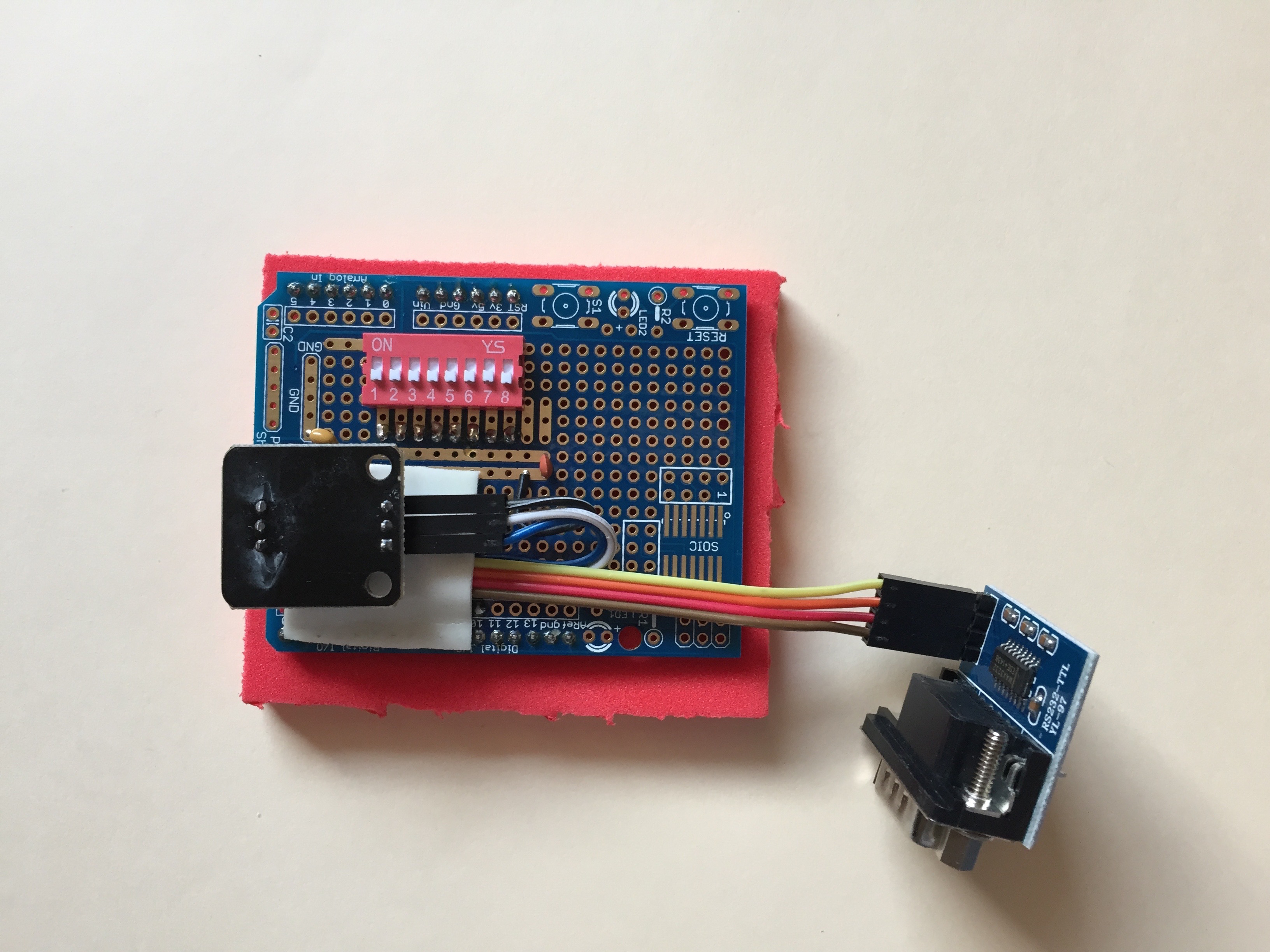
Figure CP2.13. Ready To Mount The IR Receiver
Remove the protective top sheet from the foam, align the infrared receiver board, and push it
upside down onto the mounting foam as shown in Figure CP2.14. The IR lens must face the edge
of the Proto Shield and the pins must reach backward into the middle of the board.
Push the connectors onto the IR receiver board - color-D (blue in Figure CP2.14) to the DATA pin,
color-V (white in the Figure) to the VCC pin, and color-G (black in the Figure) to the GND pin.
Figure CP2.14. IR Receiver Attached To The Proto Shield
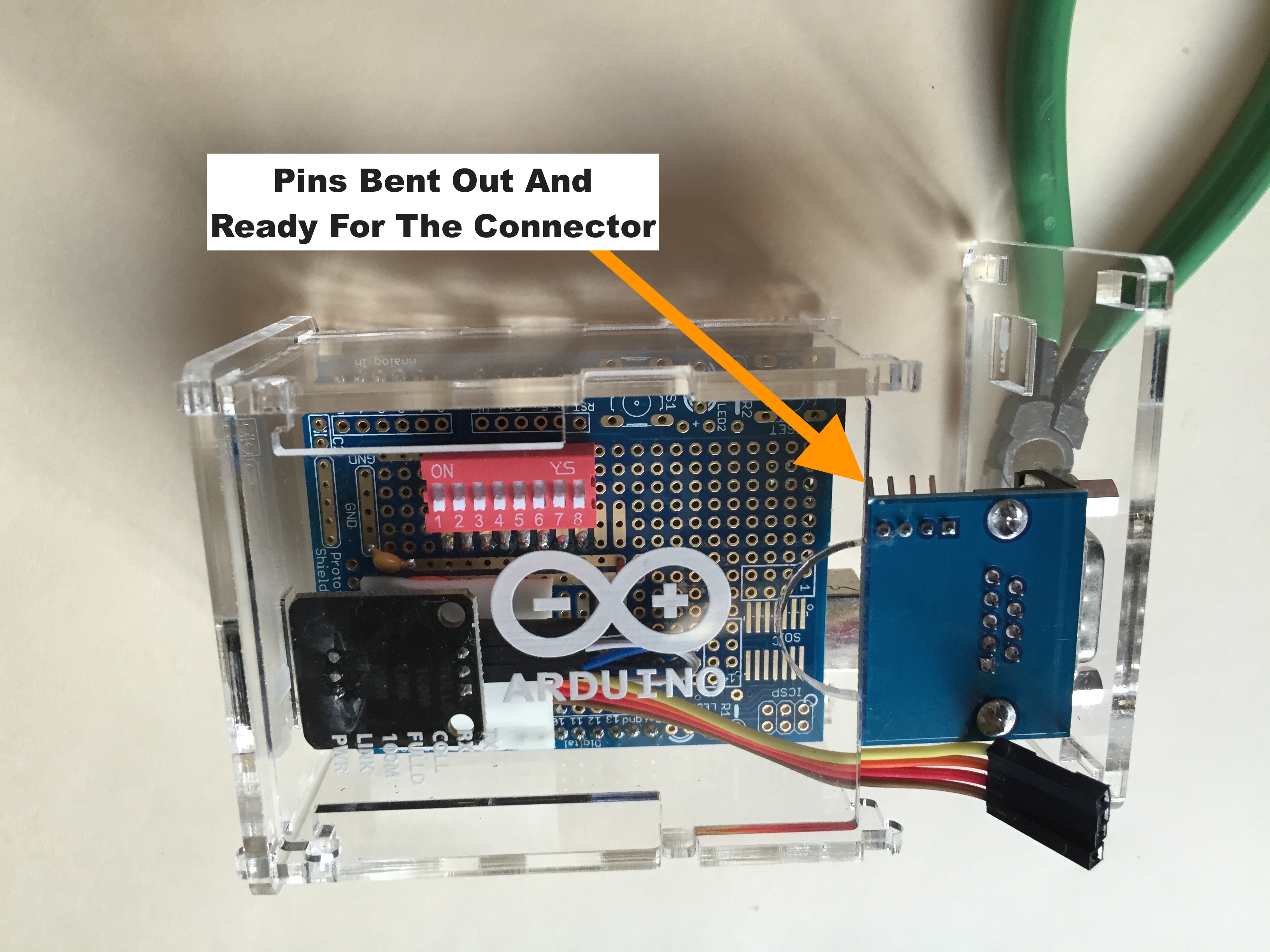
Using a small pair of pliers carefully bend the pins on the RS232 interface board outward to about
45 degrees. Be sure to bend them at the top of the plastic, not at the circuit board.
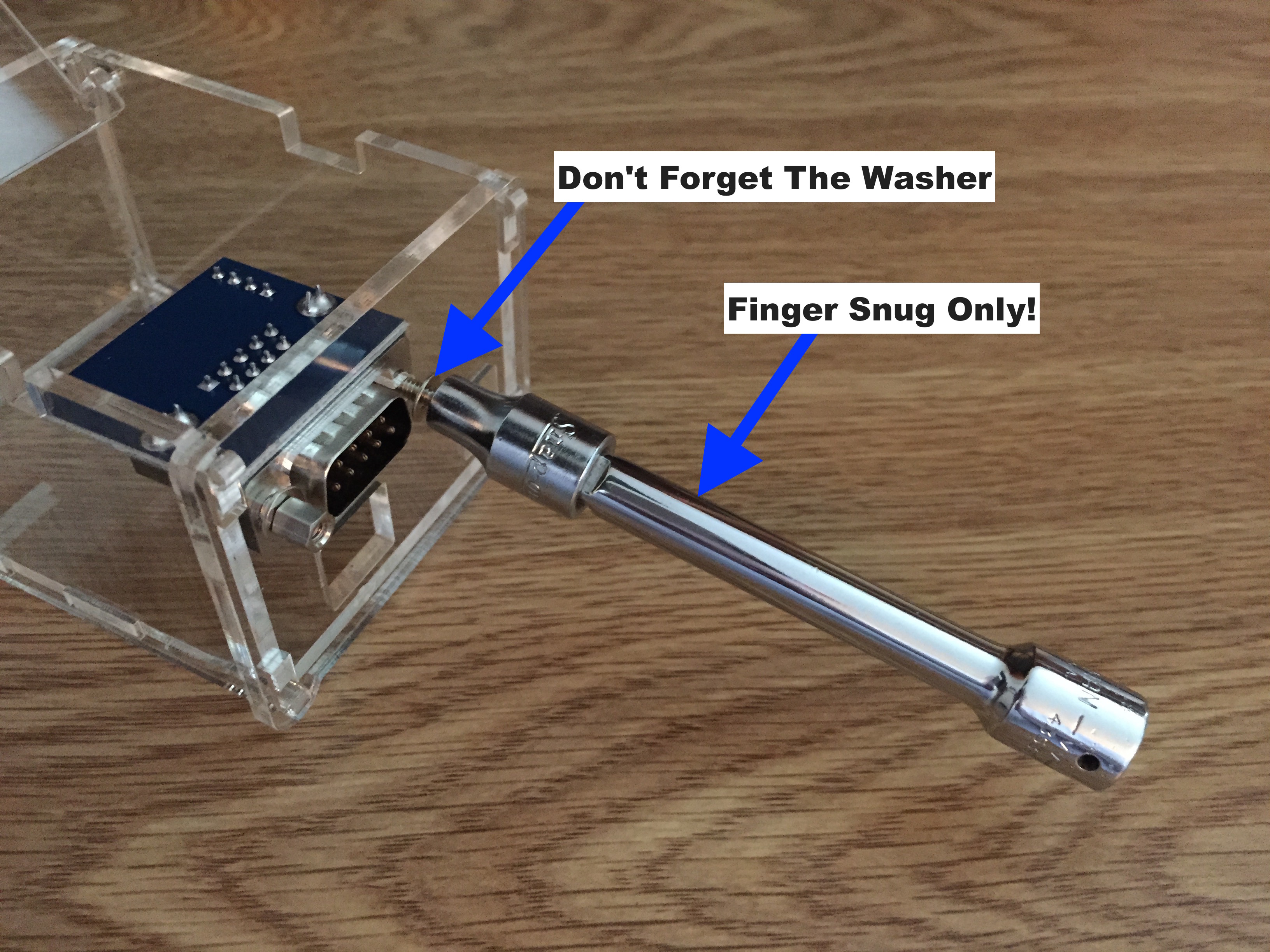
Attach the RS232 connector board to the enclosure using the 18mm UNC Jack Post screws and washers
provided. The washers must be on the outside of the enclosure. The socket extension shown in
Figure CP2.15 is for finger twirling convenience. The enclosure is a sturdy acrylic - but do not
over tighten the screws.
Figure CP2.15. Mount The RS232 Connector To The Enclosure
To complete the Proto Shield set the default factory configuration on the dipswitch. That is,
set pins 2 and 5 to ON and all others OFF.
You are almost ready for the final assembly - joining the completed Proto Shield to the
motherboard. But before doing this, make a check of the lead length of the motherboard. If
some are too long to comfortably fit in the acrylic enclosure they must be trimmed as shown in
Figure CP2.16.
Figure CP2.16. Check Lead Length On The Motherboard
Controller 2020 Final Assembly
Whether you built the kit or ordered an assembled Controller 2020, the final step is to press
the Proto Shield onto the Arduino board. Well, almost the final step. The real final step is
to put the circuit boards into the enclosure - but we'll get to that.
Have you been using proper anti-static precautions? Good. Keep it up.
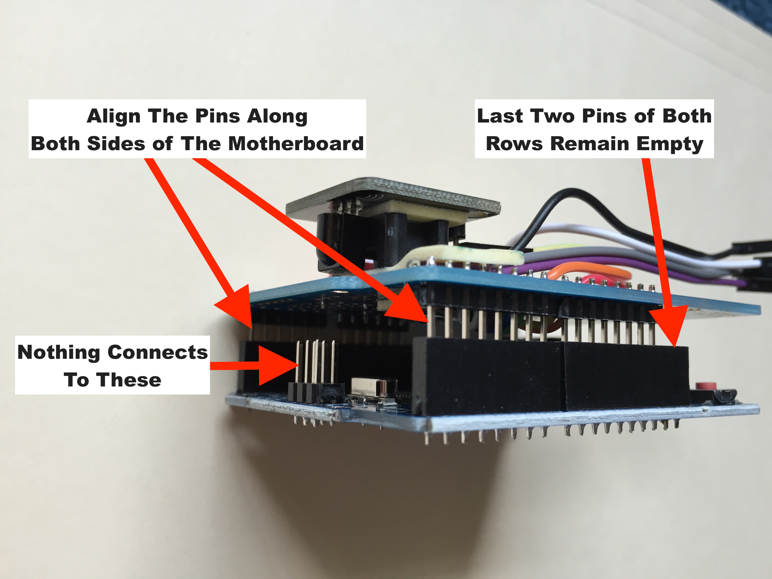
Align the Proto Shield pins with the motherboard as shown in Figure CP2.17 and press gently and
evenly around the board until all the pins are well seated.
Note: No pins connect to the final two motherboard socket holes for both rows of sockets. On
one side you will have two strips of 8 pins connecting to pins 0 to 7 and pins 8 to 13 plus GND and AREF.
On the other side you have two strips of 6 pins connecting to pins A5 to A0 and Vin to Reset.
This seems like a good time to mention the care you should take when, some day in the future,
you decide to remove the Proto Shield from the motherboard. As you pull, it is very easy to
have one side come lose causing the board to twist in you hand - breaking some pins and giving
you a very cool row of bleeding puncture wounds. Yep, I've done it - so far not on this project.
Anyway, to remove the Proto Shield work your way around and around the board lifting only a little
at a time. Try to get the entire board to come free of the sockets at the same time.
Figure CP2.17. Align The Proto Shield Pins With The Motherboard
Now you are truly ready for the final step - placing the circuit boards in the enclosure.
Your work should look something like Figure CP2.18. Push the ribbon cable connectors onto
the RS232 pins. Make sure to get the right wires on the pins.
Figure CP2.18. Caption MountTheRs232_full
Now put the acrylic back panel back on the enclosure. Remember, hang the top on the catches,
compress the bottom springy things, and gently snap together. Gently - we don't want to break
anything now!
Figure CP2.19. Put The Boards In The Enclosure
The back of your enclosure should look like Figure CP2.20.
Note: The motherboard in the kit may vary. This Figure CP2.20 shows one with a full size USB
connector. Other versions of the motherboard will not have this.
Figure CP2.20. Rear of The Enclosure After Assembly
The front of your enclosure should look like Figure CP2.21.
Figure CP2.21. Front of The Enclosure After Assembly
Congratulations. You have completed the assembly of the Controller 2020. Go play with it!
Construction Project 3: Modifying A Serial Cable For The Controller 2020
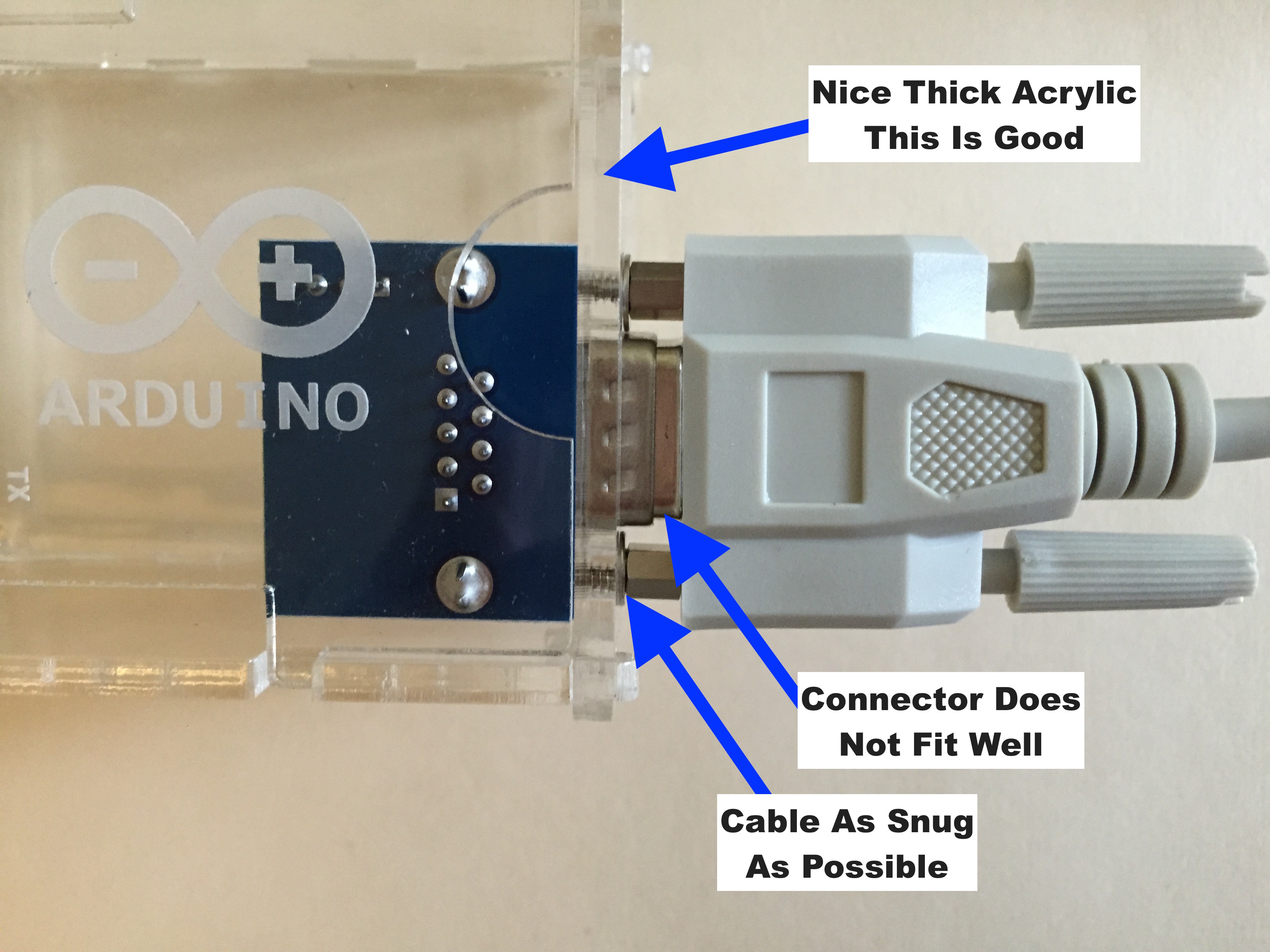
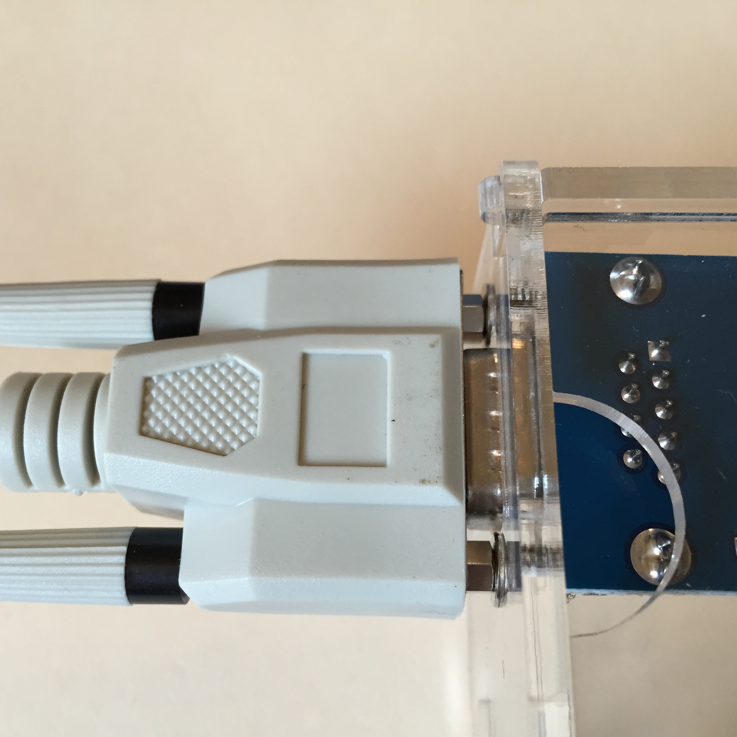
The thick acrylic of the Controller 2020 enclosure allows it to be sturdy but prevents a normal serial
cable from fully seating on the DB9 connector. The enclosure is beautiful, so we are going to let that
alone and instead modify a serial cable to make it fit better.
I sell a cable (here) that works well
but this is how to modify one from your junk box.
Figure CP3.1. Cable Connector Poor Fit Before Modification
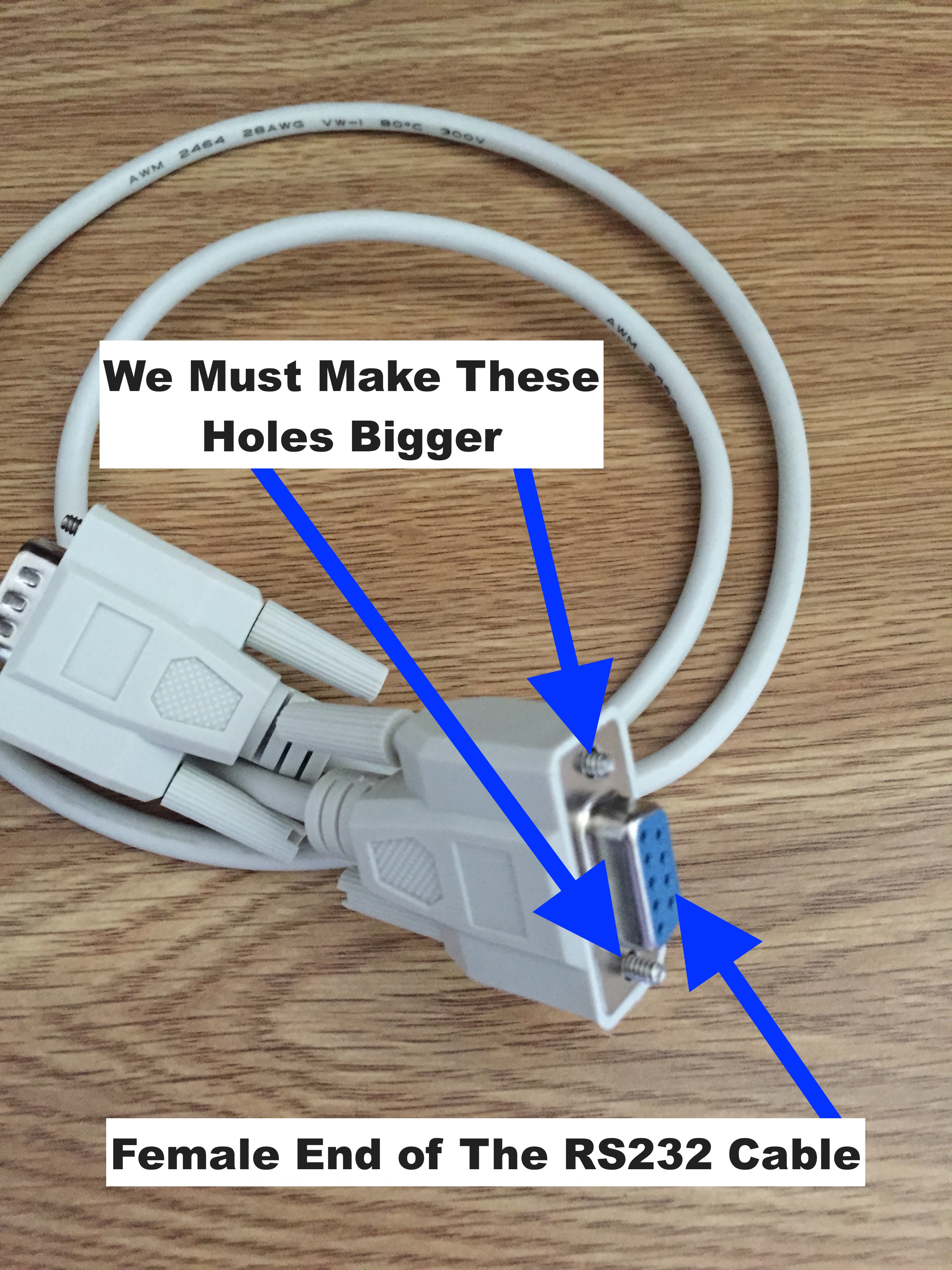
We must drill out the thumbscrew holes in the cable to allow the UNC Jack Post screws of the connector
mounted on the acrylic to recess below the face of the cable.
Figure CP3.2. End of The Cable Before Modification
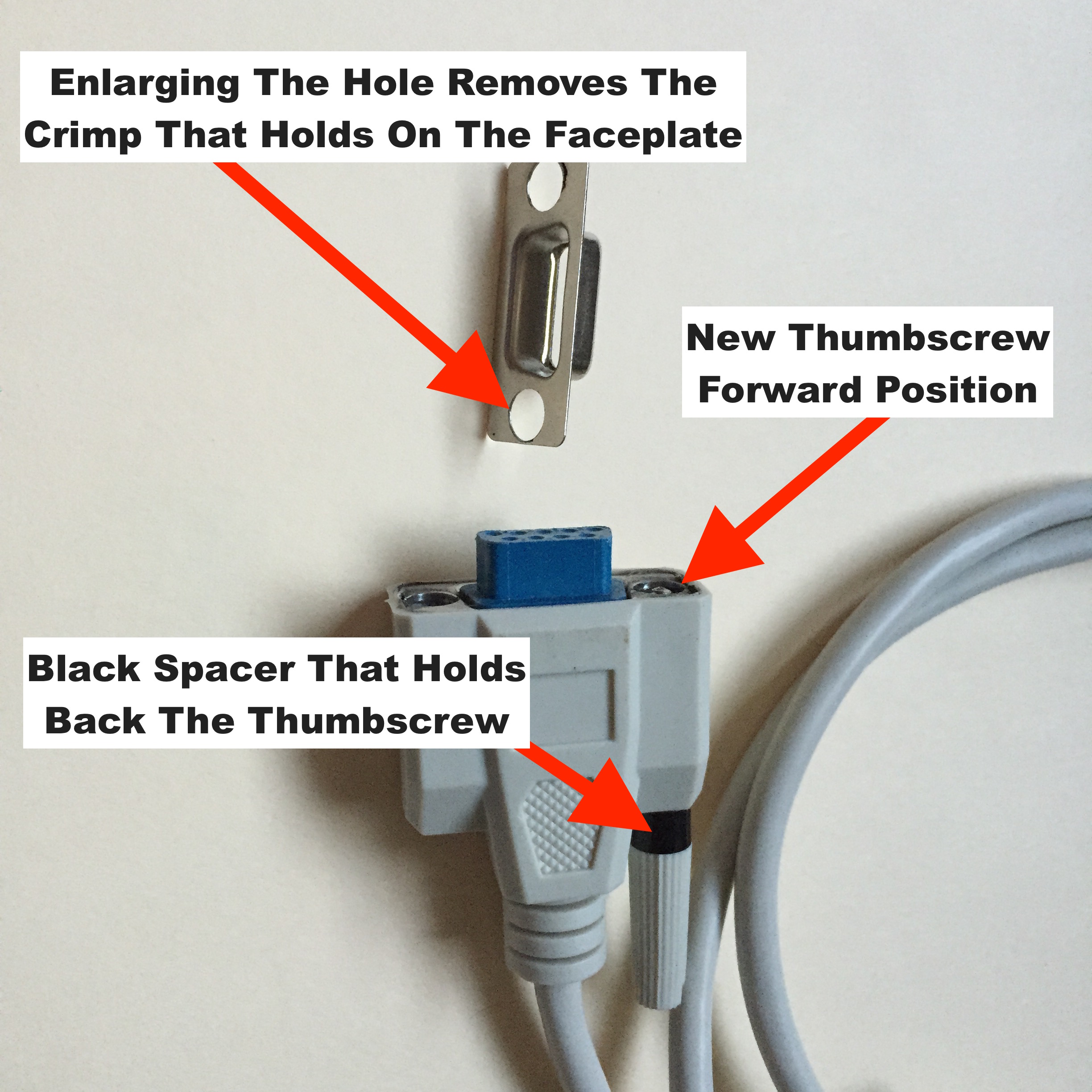
The face of the connector is actually two pieces of metal. They are held together by a slight crimp
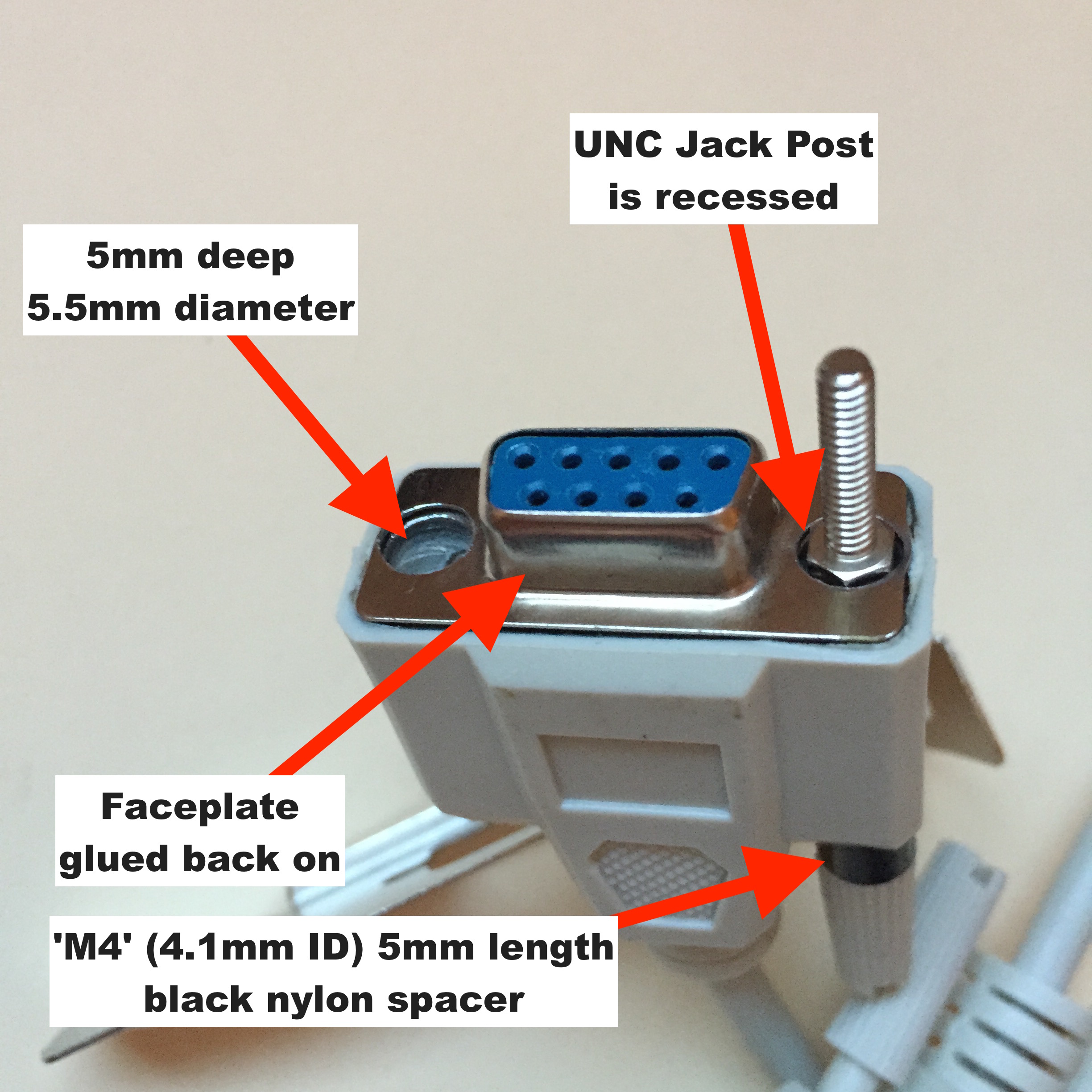
in the metal at the screw holes. Remove the thumbscrews and drill out these holes to 5.5mm diameter
and a depth of 5mm.
Very Important: Do not drill the holes beyond 5mm deep. If you drill too deeply you will
destroy the threads moulded into the plastic that keep the cable mounting thumbscrews from falling out.
When the holes are drilled the crimp is removed and the faceplate comes off as shown in Figure CP3.3.
For safety, put the cable in a vice to prevent the loose faceplate from spinning in your hand.
I found that drilling out the holes with a power drill grabs and warps the metal. The best way I
found to do this is with a Dremel tool and a 5.5mm burr bit. The high speed of the Dremel prevents
catching and bending the metal. Use a stop or brace to prevent drilling deeper than 5mm.
Interesting information: A #3 drill bit is 0.213", 5mm is 0.197", 5.5mm is 0.2165", and the
clearance hole for an M5 screw is 0.201".
Figure CP3.3. Modify The Cable Connector Step 1
Drilling the holes leaves plastic and metal residue that blocks the thumbscrew holes and
may pose a danger to electronics if it falls out on a circuit board. I clean out the
residue with a #3 drill bit in a hand-held tool and a vacuum. I found a good way to open
the thumbscrew holes is to push a 3d 1.25" finishing nail through from the back. Using
a drill to reopen the thumbscrew holes tends to damage the threads in the plastic housing.
Glue the faceplate back on the connector and let it dry completely.
Figure CP3.4. Connector Modified To Allow Recessed Jacks
Reinsert the cable mounting thumbscrews with spacers as shown in Figure CP3.5.
The spacers used have a length of 5mm and are made for M4 screws. They have an
inside diameter of 4.1mm. Spacers are needed to hold the cable mounting thumbscrews
in their new position so they can pull against the connector and hold it tight.